Charged particle optical system and scribing apparatus

a technology of optical system and charge particle, applied in the field of charge particle optical system, can solve problems such as uniform deformation of members, and achieve the effects of reducing the distribution of gaps, shortening the arrangement distance, and enhancing space efficiency

Inactive Publication Date: 2014-11-11
CANON KK
View PDF25 Cites 0 Cited by
  • Summary
  • Abstract
  • Description
  • Claims
  • Application Information

AI Technical Summary

Benefits of technology

[0007]The optical system according to the present invention can reduce the distribution of the gaps between electrodes in the deflector, a change of a gap between elements for which an optical system is used, and the like. In apparatuses such as a charged particle scribing apparatus, it generally contributes to the enhancement of the space efficiency, assembling accuracy and alignment accuracy of the optical system to assemble a plurality of elements to be integrated or shorten the arrangement distance, and imparts higher performance to the apparatus due to the reduction of deflection error and the like. However, on the other hand, the method occasionally causes a problem that deforming stress due to generated heat in a member such as a stop aperture array which receives charged particles, is transmitted to an adjacent member and ununiformly deforms the member. According to the present invention, the above described problem is solved and an improved balance between the minimized configuration and the maintenance of the high performance is accomplished.

Problems solved by technology

However, on the other hand, the method occasionally causes a problem that deforming stress due to generated heat in a member such as a stop aperture array which receives charged particles, is transmitted to an adjacent member and ununiformly deforms the member.

Method used


Image

  • Charged particle optical system and scribing apparatus
  • Charged particle optical system and scribing apparatus
  • Charged particle optical system and scribing apparatus

Examples


example 1

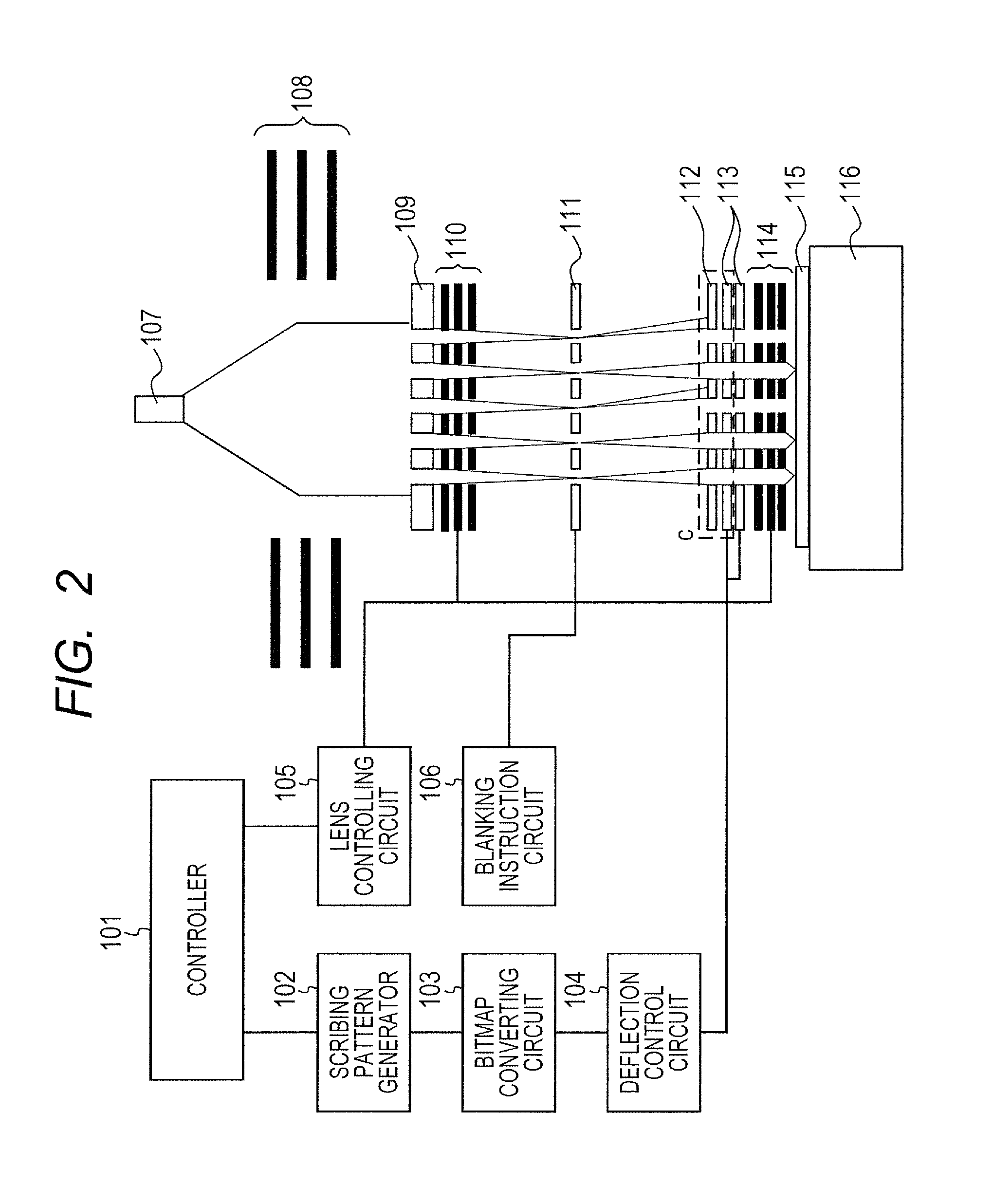
[0031]FIG. 2 illustrates a configuration of a charged particle scribing apparatus using a charged particle optical system of the present invention. Here, the charged particle is an electron. Electron beams are emitted from an electron source 107, are converted into parallel beams by a collimating lens 108, and are irradiated on an aperture array 109. A plurality of the electron beams which have been divided by the aperture array 109 are individually focused by a focusing lens array 110 that is controlled by a lens controlling circuit 105, and form images on a blanker array 111. The blanker array 111 is a device having individually deflecting electrodes therein. The blanker array turns the individual beams ON / OFF according to a scribing pattern based on a blanking signal generated by a scribing pattern generator 102, a bit map converting circuit 103, and a blanking instruction circuit 106. When the beam is in the ON state, a voltage is not applied to the deflecting electrodes of the ...

example 2

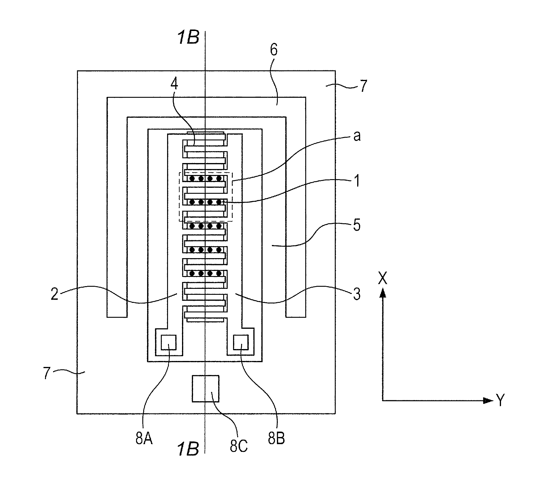
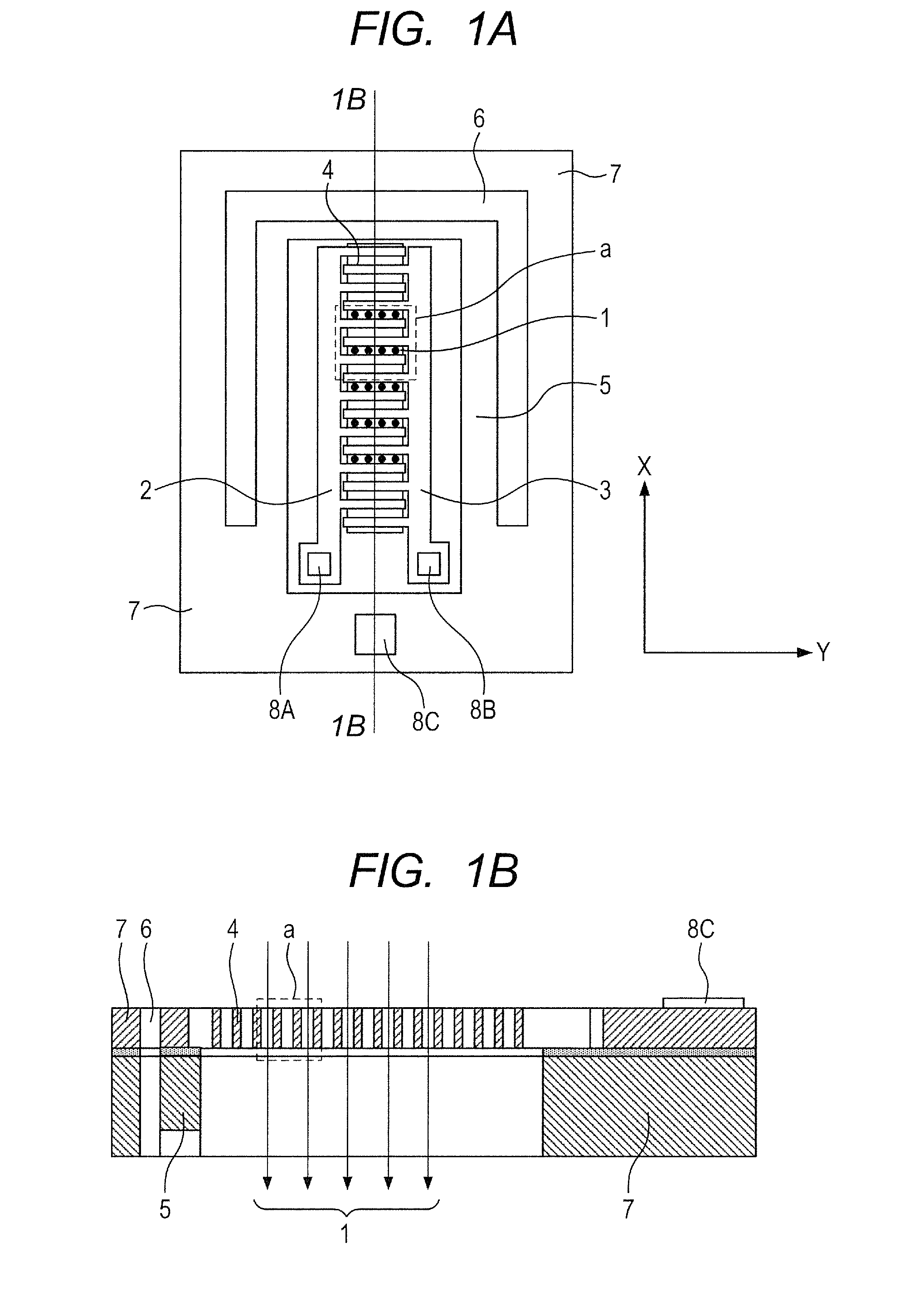
[0042]Example 2 of the present invention will be described below with reference to FIGS. 6A and 6B. The portions having the same functions and effects as in Example 1 are denoted by the same symbols, and the description will be omitted. The present example is different from Example 1 in a point that two electrostatic deflectors 113 are used so as to form two-stage deflectors. FIG. 6A illustrates a configurational cross section of a unit of the present example which almost corresponds to a unit shown by a dashed line c of FIGS. 2A and 2B. The two electrostatic deflectors 113a and 113b are assembled under a stop aperture array 112 as is illustrated in the figure.

[0043]In the present example, the electrostatic deflectors 113a and 113b have a cantilever beam structure pivotal in relation to a fixing portion 7 by a stress suppressing structure 6 (slit), as is illustrated in FIGS. 1A and 1B. The cantilever beam structure of the two electrostatic deflectors is assembled so that fixed ends ...

example 3

[0051]Example 3 of the present invention will be described below with reference to FIG. 7A. The portions having the same functions and effects as in Example 1 are denoted by the same symbols, and the description will be omitted. The present example is different from Example 1 in a stress suppressing structure which an electrostatic deflector 113 has. FIG. 7A illustrates a top plan view of an electrostatic deflector 113. A spring 6 having a spring constant in the direction shown by the arrow k is arranged as the stress suppressing structure. Even though deformation Δx is transmitted to a fixing portion 7, an electrode supporting portion 5 receives only a deforming force of kΔx due to the spring constant k. The deforming force transmitted to the electrode supporting portion 5 can be reduced by appropriately selecting the spring constant k.

[0052]In addition, the spring 6 illustrated in the figure has such a structure that the spring 6 is ductile in the arrow k direction but is firm in ...


PUM


Abstract

An optical system for a charged particle includes a first member though which a charged particle beam is transmitted and a second member to control optically the charged particle beam transmitted through the first member. The second member has a fixing portion fixed to the first member. A slit is arranged between a part of the second member and the fixing portion to separate the part of the second member from the fixing portion, such that the part of the second member is a cantilever beam structure pivotal in relation to the fixing portion.

Description

BACKGROUND OF THE INVENTION[0001]1. Field of the Invention[0002]The present invention relates to a charged particle optical system which is used in an apparatus that uses a charged particle ray therein such as an electron beam, and a scribing apparatus using the same.[0003]2. Description of the Related Art[0004]An opt-electronic element for controlling the optical properties of an electron beam is used in an electron beam exposure apparatus. In the opt-electronic element, a deflector is an element which deflects an electron beam so as to make the electron beam scan a desired region and scribe an image on the region. WO 2010 / 125526 discloses an electrostatic deflector which simultaneously deflects a plurality of electron beams with an electric field. The deflector has a slim comb tooth structure in which two electrodes dovetail with each other while being separated by a gap, and deflects a beam row with an electric field which has been generated in the gap of the comb tooth structure...

Claims


Application Information

Patent Timeline
Patent Type & Authority Patents(United States)
IPC IPC(8): H01J37/04H01J37/317H01J29/74H01J37/147
CPCH01J37/045B82Y40/00H01J2237/03H01J37/3177H01J2237/0435H01J2237/151B82Y10/00
Inventor KATO, TAKAHISA
Owner CANON KK
Why Eureka
Try Eureka