
Light transmissive substrate, method of making transmissive substrate, surface light source unit, polarizing plate, and liquid crystal device

a technology of transmissive substrate and light, which is applied in the field of light transmissive substrate, a method of making transmissive substrate, a surface light source unit, a polarizing plate, and a liquid crystal display. it can solve the problems of uneven brightness, interference fringe, deterioration of display uniformity, etc., and achieves the effect of preventing moire, reducing thickness and high brightness

Active Publication Date: 2014-11-25
FUJIFILM CORP
View PDF10 Cites 11 Cited by
  • Summary
  • Abstract
  • Description
  • Claims
  • Application Information

AI Technical Summary

Benefits of technology

[0013]Although the prism sheet according to JP 2007-304553A is excellent in high brightness and prevention of moire, the layer containing light diffusing particles increases the total thickness of the prism sheet, which is disadvantageous for LCD thickness reduction.
[0014]An object of the invention is to provide a surface light source unit that provides high brightness, prevents moire, and contributes to thickness reduction and an LCD including the surface light source unit. Another object of the invention is to provide a light transmissive substrate useful in the surface light source unit.
[0038]According to the invention there is provided a surface light source unit that achieves high brightness, prevents moire, and contributes to thickness reduction.

Problems solved by technology

If the haze of the diffuser film is reduced, i.e., the total transmittance is raised in order to maintain the front brightness, such can result in deterioration of display uniformity (e.g., unevenness of backlight) or occurrence of an interference fringe such as Moire.
It has also been turned out that, when such a diffuser film having projections on its surface as disclosed in JP 2000-75134A is disposed adjacent to a prism sheet with no diffuser sheet therebetween a, the prism sheet is potentially scratched by rubbing against the diffuser film to cause spot unevenness of brightness.
This problem has proved to emerge, particularly with mobile LCDs such as notebook computers which are subject to Vibration or mechanical shock and with LCDs having a slimmed backlight unit in which a diffuser film and a prism sheet are apt to contact with each other.
Although the prism sheet according to JP 2007-304553A is excellent in high brightness and prevention of moire, the layer containing light diffusing particles increases the total thickness of the prism sheet, which is disadvantageous for LCD thickness reduction.

Method used


Image

  • Light transmissive substrate, method of making transmissive substrate, surface light source unit, polarizing plate, and liquid crystal device
  • Light transmissive substrate, method of making transmissive substrate, surface light source unit, polarizing plate, and liquid crystal device
  • Light transmissive substrate, method of making transmissive substrate, surface light source unit, polarizing plate, and liquid crystal device

Examples


examples

1. Preparation of Light Collecting Sheet (Member A)

1-1. Preparation of Prism Sheets P-1 and P-2

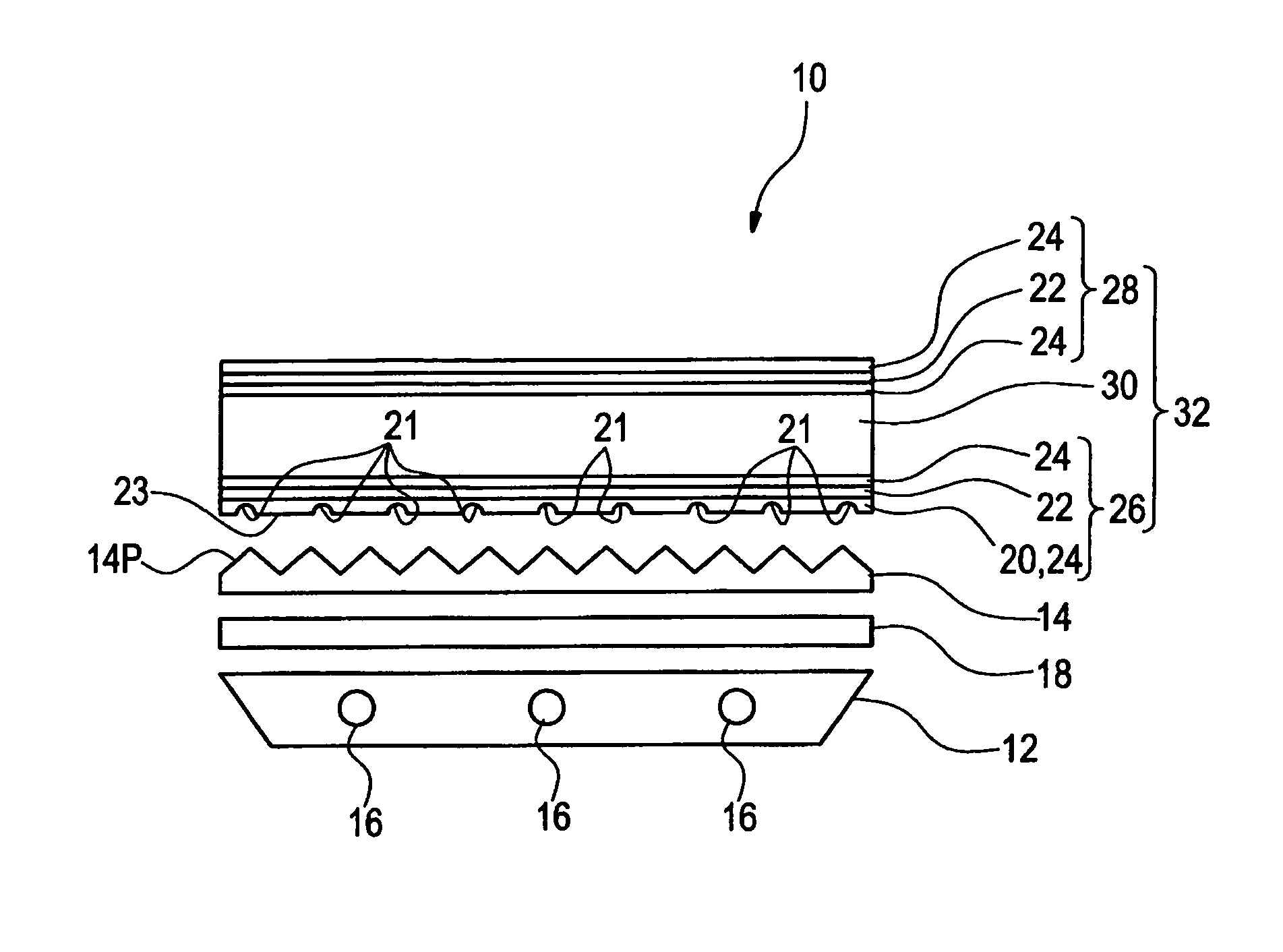
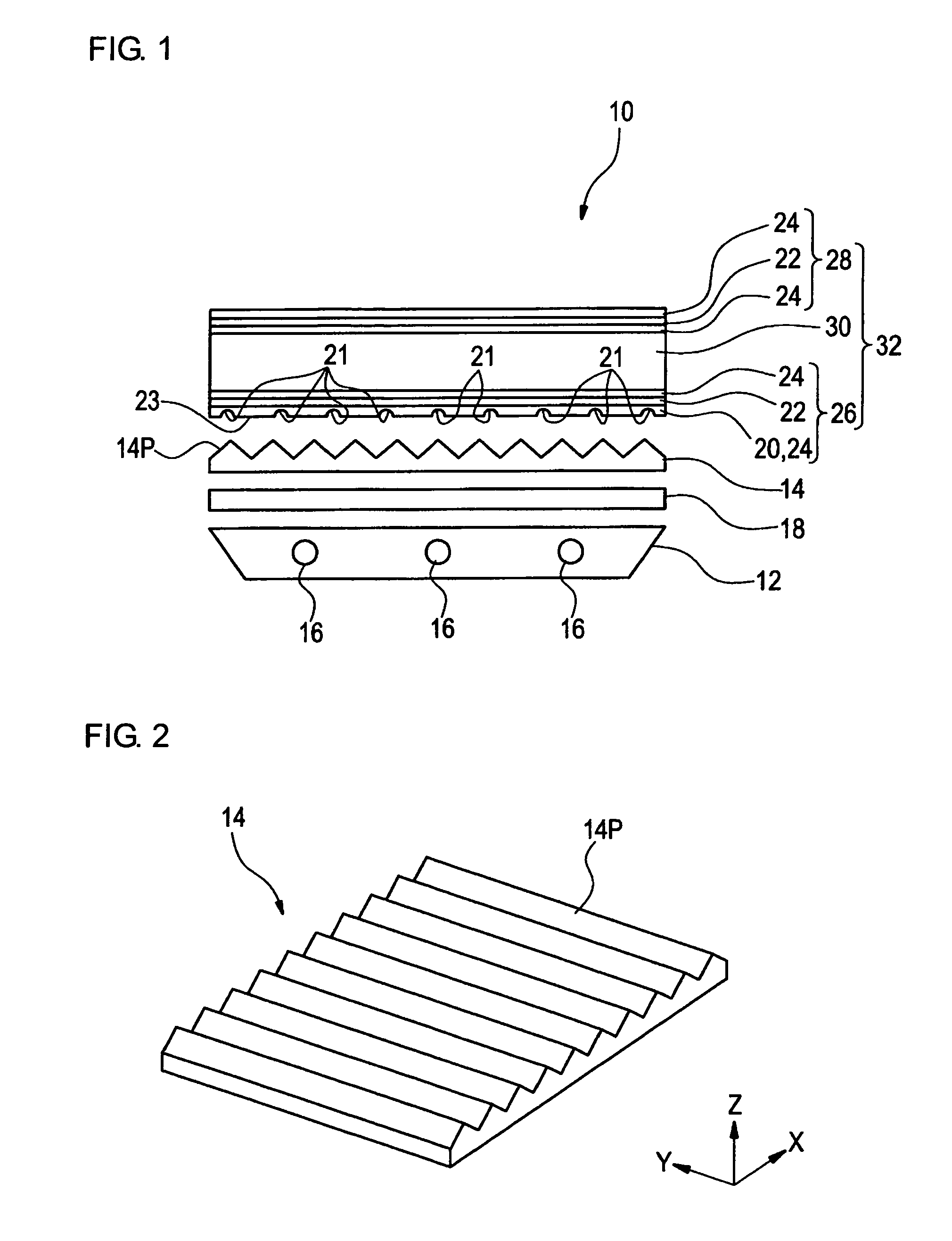
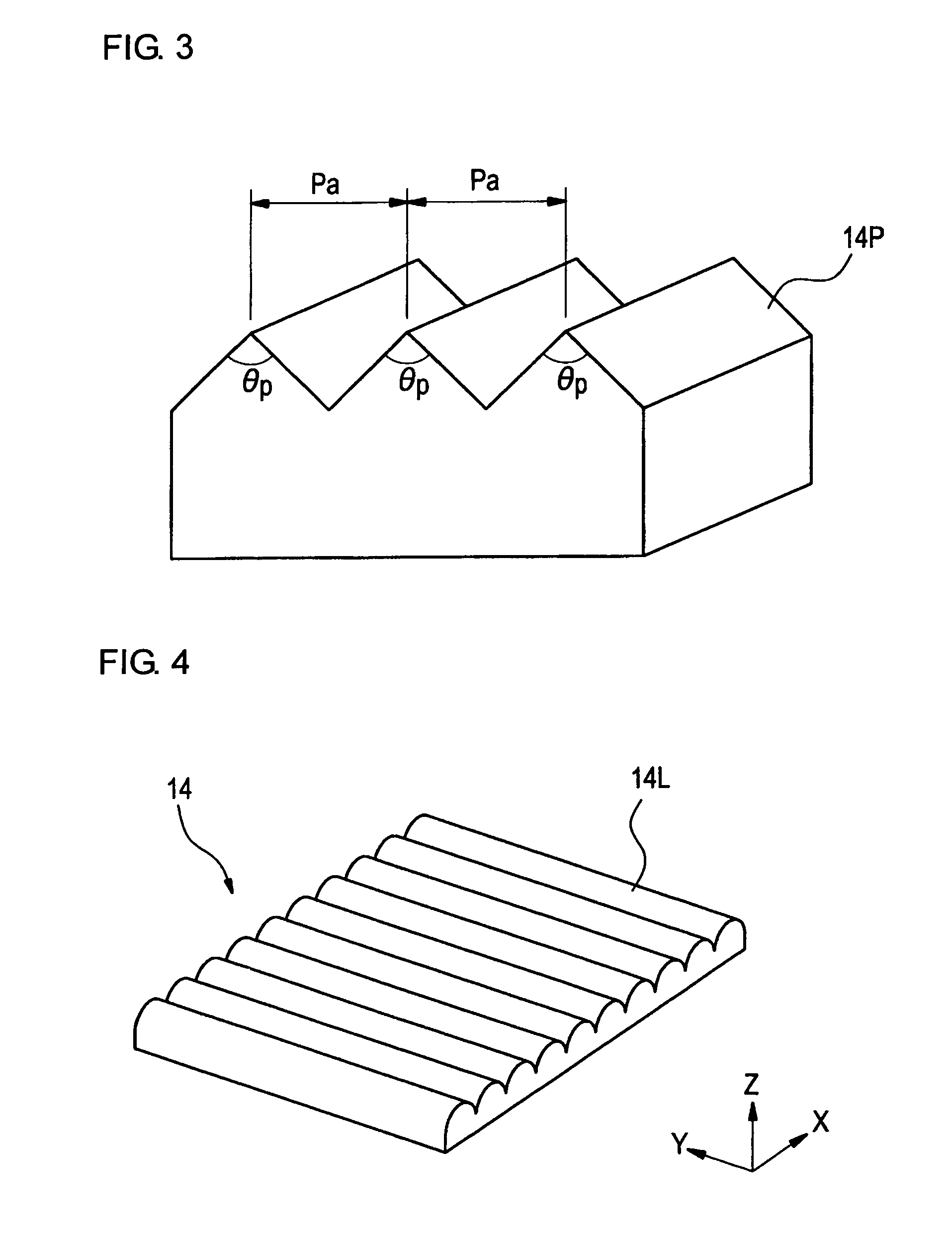
[0226]A polycarbonate resin was melt extruded to obtain prism sheets P-1 and P-2 having an array of prisms each having an isosceles triangular cross-section on its light emitting side. Prism sheet P-1 had a thickness (distance from the valley of prisms to the reverse side) of 125 μm, a prism apex angle of 90°, and a prism pitch (Pa) of 110 μm. Prism sheet P-2 had the same geometry as P-1, except for having the pitch Pa of 200 p.m.

1-2. Preparation of Prism Sheets P-101 to P-103

[0227]A curing composition having the formulation shown in Table 1 below was applied to a 80 μm thick polyethylene terephthalate film, press embossed, and photo cured to make a prism sheet, designated P-101, P-102, or P-103, having the same geometry as prism sheet P-1.

[0228]

TABLE 1Curing CompositionPrism Sheet No.(part by mass)P-101P-102P-103Pentaerythritol1077triacrylateUrethane acrylate363636(Cpd-1*1)Polybutylene gl...


PUM

PropertyMeasurementUnit
dielectric constantaaaaaaaaaa

Abstract

A surface light source unit includes, in the following order: a light source; a light collecting sheet having light collection portions on at least one side of the light collecting sheet; and a light transmissive substrate having a flat portion and recesses on at least one side of the light transmissive substrate.

Description

CROSS-REFERENCE TO RELATED APPLICATIONS[0001]This application claims the benefit of Japanese Patent Application JP 2009-229024, filed Sep. 30, 2009, the entire content of which is hereby incorporated by reference, the same as if set forth at length.FIELD OF THE INVENTION[0002]This invention relates to a light transmissive substrate, a method of making a light transmissive substrate, a surface light source unit, a polarizing plate, and a liquid crystal display.BACKGROUND OF THE INVENTION[0003]Liquid crystal displays (LCDs) have recently enjoyed wide use because of small thickness, light weight, and low power consumption. An LCD includes a liquid crystal cell and a polarizing plate. A polarizing plate is usually composed of a pair of protective films and a polarizing film and obtained by stretching a polyvinyl alcohol film dyed with iodine to make a polarizing film and laminating a protective film to both sides of the polarizing film. A transmissive LCD has a polarizing plate on both ...

Claims


Application Information

Patent Timeline
Patent Type & Authority Patents(United States)
IPC IPC(8): G02F1/13G02F1/1335
CPCG02F1/133604G02F2001/133607G02F1/133611B32B2457/202G02F1/133607
Inventor YONEYAMA, HIROYUKISASADA, YASUYUKIYANAI, YUJIRO
Owner FUJIFILM CORP
Learn More