Spatial filters for high power lasers

a laser and laser technology, applied in the field of spatial filters for high-power lasers, can solve the problems of reducing beam intensity, high-spatial-frequency variations in intensity and wavefront across the beam, and reducing the risk of optical damage to laser optics, so as to reduce the vacuum requirements of the laser system, reduce the cost and pumping time, and high repetition rate

Active Publication Date: 2014-12-02
LAWRENCE LIVERMORE NAT SECURITY LLC
View PDF3 Cites 20 Cited by
  • Summary
  • Abstract
  • Description
  • Claims
  • Application Information

AI Technical Summary

Benefits of technology

[0011]Numerous benefits are achieved by way of the present invention over conventional techniques. For example, the present systems provide spatial filters that filter out intensity and phase variations above a predetermined spatial frequency. Additionally, embodiments of the present invention provide for image relaying, which restores the laser wavefront at a downstream object plane. Moreover, embodiments of the present invention provide for maintenance of beam quality in high repetition rate pulsed laser systems. Furthermore, some embodiments reduce the vacuum requirements for the laser system, thereby reducing costs and pump-down times in comparison with conventional systems. Depending upon the embodiment, one or more of these benefits may be achieved. These and other benefits will be described in more detail throughout the present specification and more particularly below.

Problems solved by technology

However, as laser beams propagate through laser optics, which are nearly always imperfect, scattering from small-scale obscurations and phase objects cause high-spatial-frequency variations in intensity and wavefront across the beam.
Such intensity variations increase risk for optical damage to laser optics, and both intensity variations and wavefront variations increase the laser spot size for subsequently focused laser beams, thereby decreasing the beam intensity.
For applications dependent on high beam intensity, this condition is undesirable.
Despite the benefits in beam quality provided by pinhole spatial filters, several problems are presented by the use of pinhole filters.

Method used


Image

  • Spatial filters for high power lasers
  • Spatial filters for high power lasers
  • Spatial filters for high power lasers

Examples


Embodiment Construction

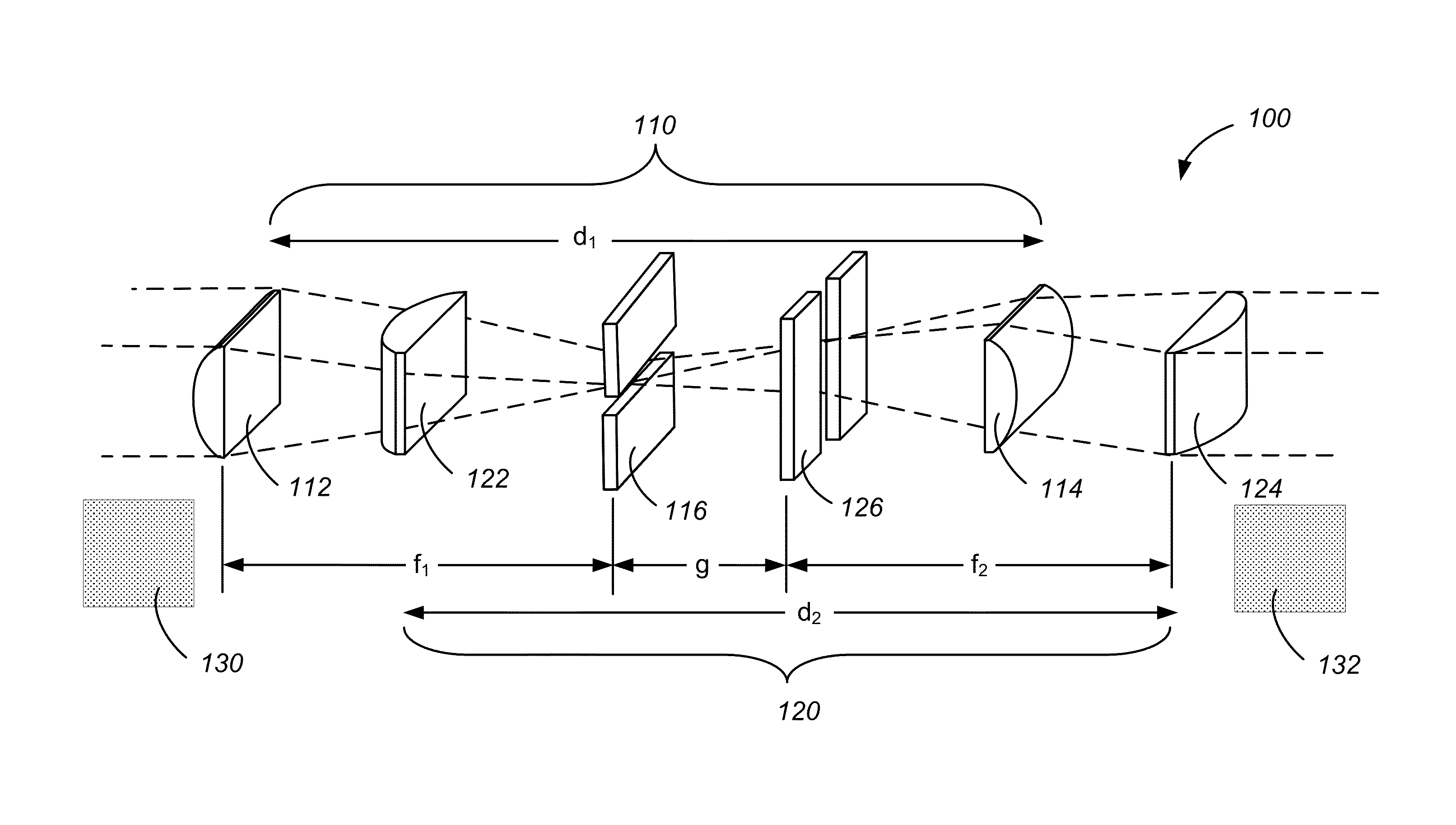
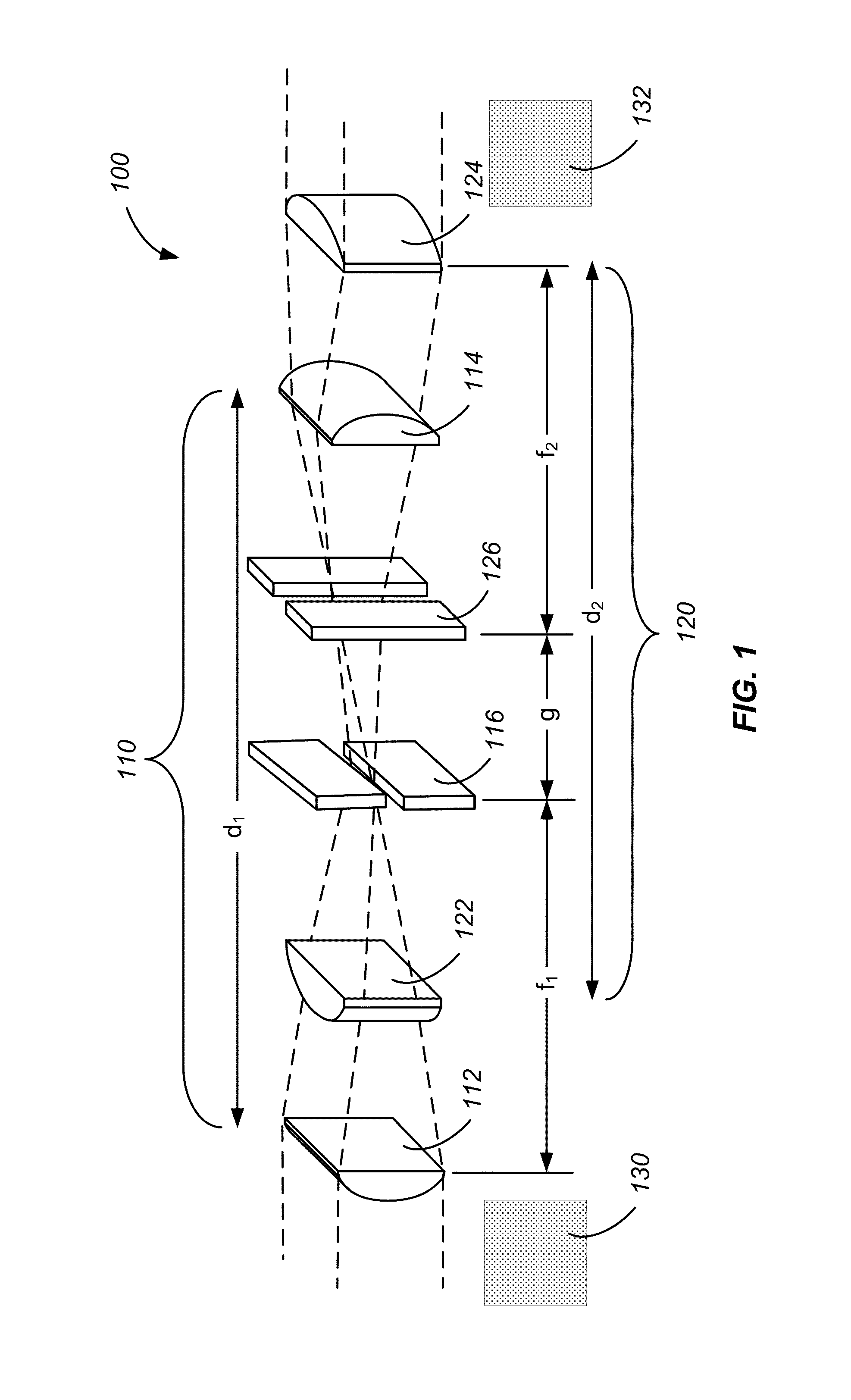
[0022]As discussed above, pinhole spatial filters have been utilized in some high power laser applications. However, pinhole spatial filters present several problems in the context of high power laser systems. Because of the high intensities associated with some high power lasers, sputtering of the material surrounding the center of the pinhole can result during operation, producing sputtered materials that may contaminate optics. Contamination of lenses by sputtered material can result in increases in laser absorption by the lenses, eventually resulting in damage to the lens. Such contamination problems are particularly troublesome in pulsed applications, where frequent sputtering events can result in pinhole wearout, with the open area at the center of the pinhole expanding as a function of time. Over time, pinhole wearout results in decreases in beam quality and system performance.

[0023]Another problem presented by the use of pinhole spatial filters for high power lasers is pinho...


PUM


Abstract

A spatial filter includes a first filter element and a second filter element overlapping with the first filter element. The first filter element includes a first pair of cylindrical lenses separated by a first distance. Each of the first pair of cylindrical lenses has a first focal length. The first filter element also includes a first longitudinal slit filter positioned between the first pair of cylindrical lenses. The second filter element includes a second pair of cylindrical lenses separated by a second distance. Each of the second pair of cylindrical lenses has a second focal length. The second filter element also includes a second longitudinal slit filter positioned between the second pair of cylindrical lenses.

Description

CROSS-REFERENCES TO RELATED APPLICATION[0001]This application claims priority to U.S. Provisional Patent Application No. 61 / 380,645, filed Sep. 7, 2010. This application is also a continuation-in-part of U.S. patent application Ser. No. 12 / 544,988, filed Aug. 20, 2009. The disclosures of 61 / 380,645 and Ser. No. 12 / 544,988 are hereby incorporated by reference in their entirety for all purposes.STATEMENT AS TO RIGHTS TO INVENTIONS MADE UNDER FEDERALLY SPONSORED RESEARCH OR DEVELOPMENT[0002]The United States Government has rights in this invention pursuant to Contract No. DE-AC52-07NA27344 between the U.S. Department of Energy and Lawrence Livermore National Security, LLC, for the operation of Lawrence Livermore National Laboratory.BACKGROUND OF THE INVENTION[0003]High power lasers provide beams of coherent radiation characterized by high beam quality. Preferably, the laser output of a high power laser is characterized by a uniform wavefront. Because they produce high power, coherent r...

Claims


Application Information

Patent Timeline
Patent Type & Authority Patents(United States)
IPC IPC(8): H01S3/06
CPCH01S3/2325G02B19/0052G02B27/46H01S3/235H01S3/0805H01S3/005H01S3/0064H01S3/2333G02B19/0014G02B27/0966G02B27/0988
Inventor ERLANDSON, ALVIN CHARLESBAYRAMIAN, ANDREW JAMES
Owner LAWRENCE LIVERMORE NAT SECURITY LLC
Why Eureka
Try Eureka