Collection structure in batteries

a collection structure and battery technology, applied in the direction of cell components, final product manufacturing, sustainable manufacturing/processing, etc., can solve the problems of high degree of wiring complexity, high overall system performance, and current generated incrementally in the surface area of the electrode, so as to improve the electrical resistance between the terminal region and a point on the carrier foil. , the effect of reducing the electrical resistan

Active Publication Date: 2014-12-09
ROBERT BOSCH GMBH
View PDF2 Cites 2 Cited by
  • Summary
  • Abstract
  • Description
  • Claims
  • Application Information

AI Technical Summary

Benefits of technology

[0010]The present invention provides an electrode, e.g., for use in a battery, that has an electrically conductive carrier foil having a terminal region for connection to an electrical circuit, which electrode is characterized in that in order to improve electrical collection via the terminal region, the carrier foil has at least one structure element, having an elevated electrical conductivity as compared with the carrier foil, by way of which the electrical resistance between the terminal region and a point on the carrier foil is reduced.
[0011]It has been found, surprisingly, that the provision of such a structure element can greatly decrease or even eliminate the risk of local or zonal overheating of the battery.
[0012]The electrically conductive structure increases the conductivity of the electrode in a freely selectable preferred direction, so that the voltage drop across, in particular, large electrode surfaces can be kept low. Local disruptions also have much less of an effect, since a current path that is sufficiently dimensioned thanks to the structure element can intercept current spikes.
[0017]“Applied by electrodeposition” means that metal layers are deposited onto the surface of the carrier foils. This can occur both autocatalytically or by application of a suitable deposition current as a direct current or even a pulsed current. In principle, all electrodeposition methods known from the field of circuit board production for the application of structures can be used in this context. The structures can be deposited at any thickness. They are preferably deposited at a thickness between 5 μm and 500 μm. Deposition at this thickness on the one hand ensures sufficient conductivity for the structure, and on the other hand the weight added by the structure can be minimized.
[0020]Provision can likewise be made that, for example using a photoresist and a mask, a suitable structure is applied onto a, for example, copper foil, and excess material is removed from the carrier foil in an etching step. The result is that the weight of the carrier foil is reduced, and at the same time conductive structure elements are formed.

Problems solved by technology

As a rule, multiple small cells are connected together, with a high degree of wiring complexity, for a high-performance overall system.
The difficulty then exists, during the charging and discharging of such a battery, that the current generated incrementally in the surface area of the electrode flows out of all regions of the electrode toward the collector.
Electrical conduction is often associated with losses, which become evident as local heating of the battery.
Defects in the ideal disposition, for example an irregular coating, excessively large particles in the layer, inhomogeneous compression of the electrodes, or the like, result additionally in an inhomogeneous current flow in the electrode.
Local or zonal overheating of the battery can therefore occur; this can result in premature aging, capacity loss, or even thermal damage to the battery.

Method used


Image

  • Collection structure in batteries
  • Collection structure in batteries
  • Collection structure in batteries

Examples


Embodiment Construction

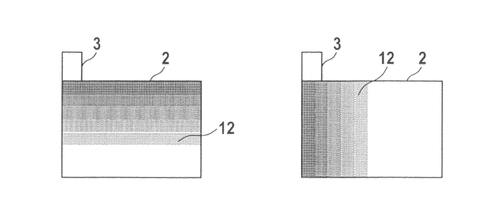
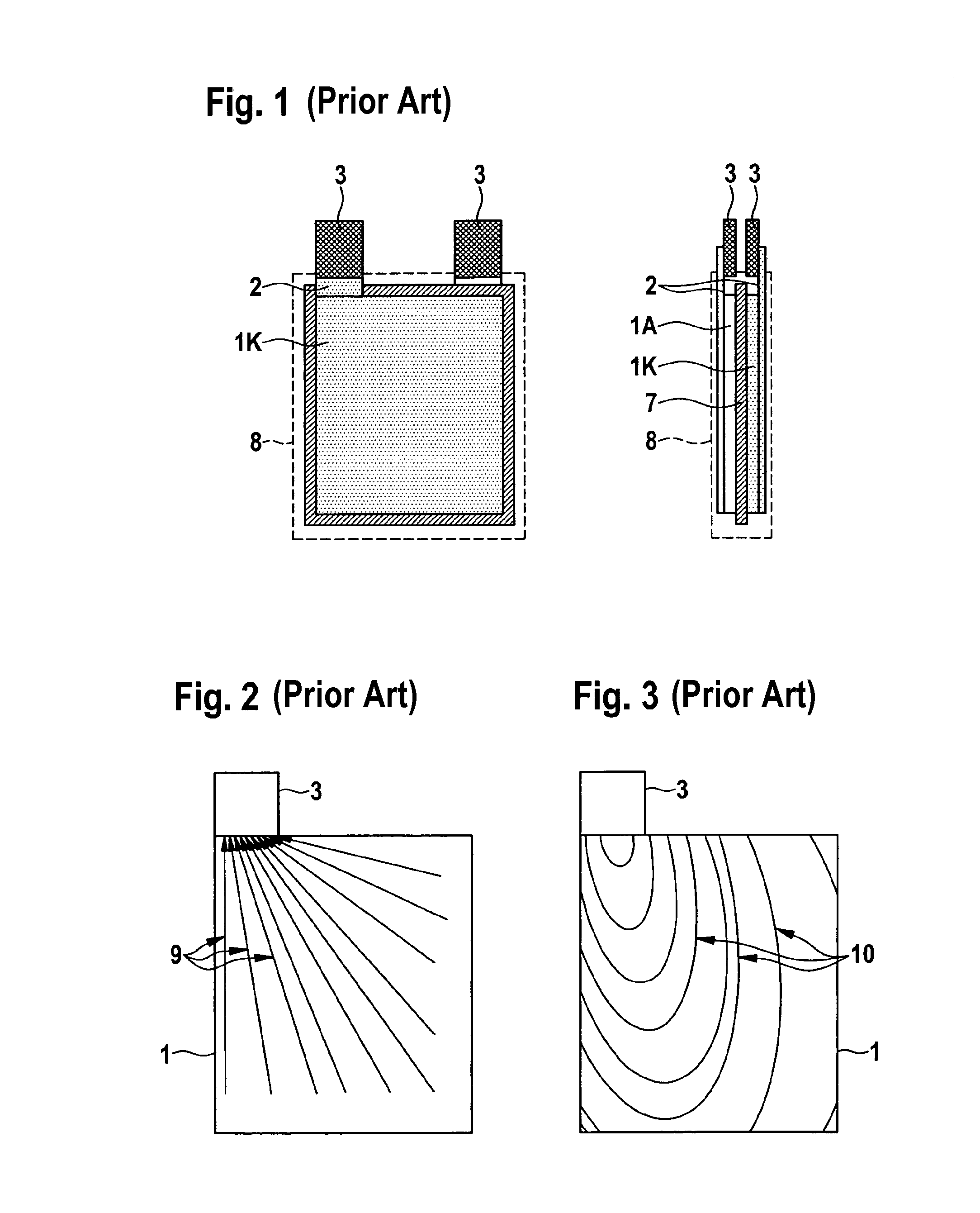
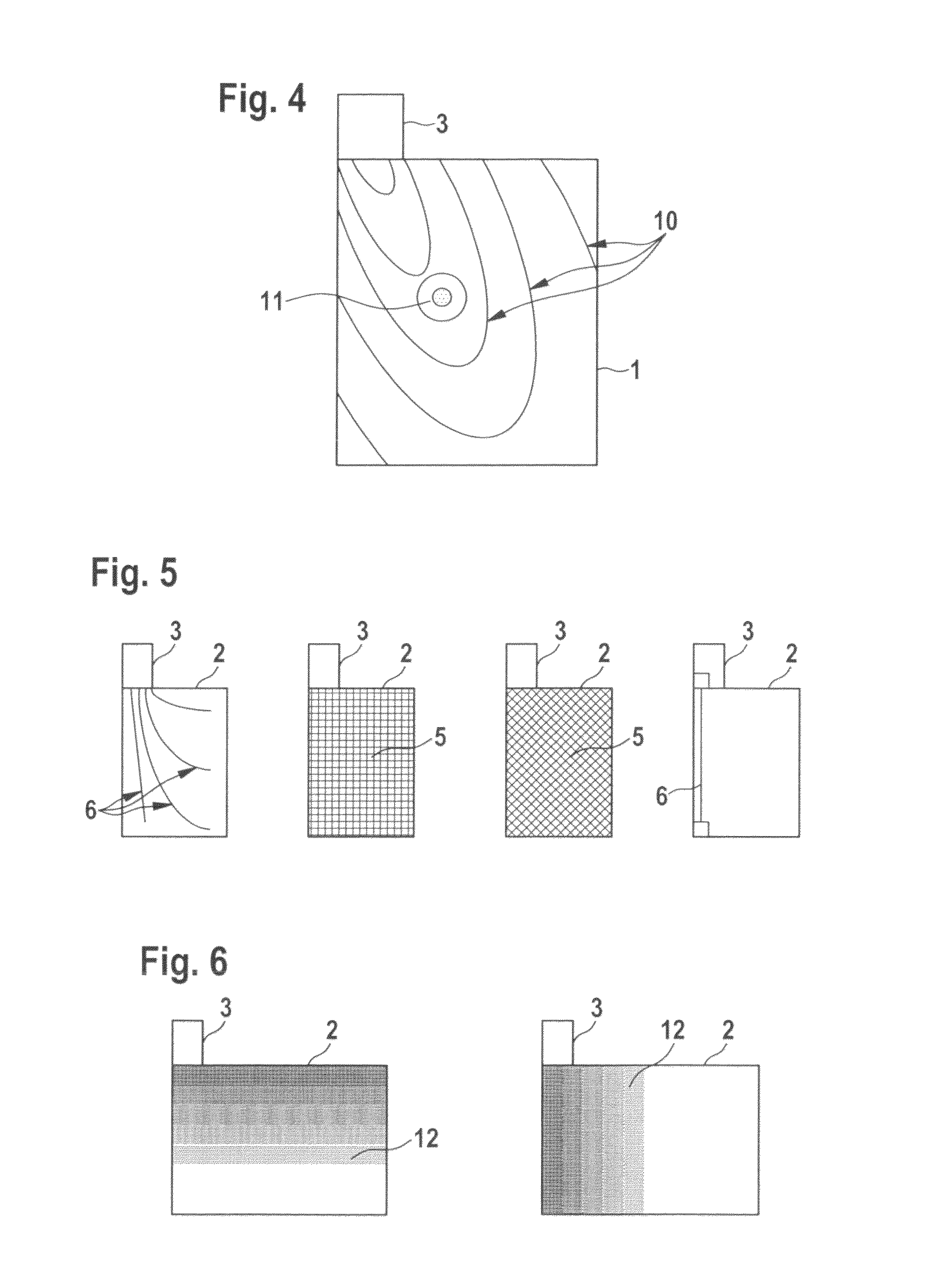
[0042]FIG. 1 shows the general construction of a battery pack. The battery pack is made up of an anode 1A and a cathode 1K that are separated from one another by a separator 7. Separator 7 acts in electrically insulating fashion, but is permeable to ions. Suitable materials for use as separators 7 are, for example, microporous plastics, or glass-fiber or polyethylene mats. Cathode 1K and anode 1A are constructed from a carrier foil 2 and applied cathode and anode material, respectively. Copper foil, nickel foil, or aluminum foils, for example, can be used as carrier foil 2. Lithium mixed oxides such as Li4Ti5O12, LiCoO2, LiNiO2, LiMn2O4, or lithium iron phosphate (LiFePO4), for example, can be used as cathode material. Graphite-containing pastes, nanocrystalline amorphous silicon, or tin dioxide (SnO2), for example, can be used as anode material. Electrodes 1 have a terminal region 3 which serves as an electrical collector and through which electrical contacting of electrodes 1 to a...


PUM

PropertyMeasurementUnit
thicknessaaaaaaaaaa
thicknessaaaaaaaaaa
electrically conductiveaaaaaaaaaa

Abstract

An electrode in a battery, e.g., a lithium-ion battery, has an electrically conductive carrier foil including (i) a terminal region for connection to an electrical circuit and (ii) at least one electrically conductive structure element configured to reduce the electrical resistance between the terminal region and a point on the carrier foil in order to improve electrical collection via the terminal region.

Description

BACKGROUND OF THE INVENTION[0001]1. Field of the Invention[0002]The present invention relates to improved collection structures for collecting electrical energy in batteries, e.g., a lithium-ion battery, and relates in particular to an electrode which has an electrically conductive carrier foil having a terminal region for connection to an electrical circuit, and in which, in order to improve electrical collection via the terminal region, the carrier foil has at least one electrically conductive structure element by way of which the electrical resistance between the terminal region and a point on the carrier foil is decreased.[0003]2. Description of the Related Art[0004]In order to manufacture batteries such as, for example, lithium-ion batteries, an active layer is applied onto an electrically conductive collector. For example, graphite-containing pastes or nanocrystalline amorphous silicon having lithium inclusions, or also lithium mixed oxides such as Li4Ti-5O12, LiCoO2, LiNiO2, ...

Claims


Application Information

Patent Timeline
Patent Type & Authority Patents(United States)
IPC IPC(8): H01M4/66H01M10/0585H01M10/052H01M4/72H01M4/64H01M4/70
CPCH01M4/661H01M10/0585H01M4/72H01M10/052H01M4/667Y02E60/122H01M4/70Y02T10/7011Y10T29/49115Y02E60/10Y02P70/50Y02T10/70
Inventor BAUER, HARALD
Owner ROBERT BOSCH GMBH
Why Eureka
Try Eureka