Progressive gun spring recoil system with high energy rebound

a recoil system and progressive technology, applied in the field of semiautomatic gun mainspring recoil systems, can solve the problems of reducing affecting the operation of the gun, so as to improve the ease of operation, reduce the weight of the mainspring, and facilitate the basic operation of the gun.

Inactive Publication Date: 2015-01-27
RECOIL REBOUND
View PDF7 Cites 9 Cited by
  • Summary
  • Abstract
  • Description
  • Claims
  • Application Information

AI Technical Summary

Benefits of technology

[0012]Belleville springs are designed to fit over rods (according to a minimum inner diameter) and into holes (according to a maximum outer diameter), providing an ideal addition to spring guide rod and sleeve assemblies used in firearm recoil systems. They may be used singly, or stacked to increase load (i.e. the amount of force applied to the spring) and deflection (i.e. the distance the spring(s) compresses). Increasing the number of springs in a nested stack allows for increased loads that may be applied to the spring stack. Increasing the number of springs in an inverted stack allows for increased deflection while retaining the same load or force (e.g. load or force of only one spring) across the span of the stack. In a nested-and-inverted (mixed) stack both load and deflection may be adjusted, i.e. increased or decreased as desired, based on the combination of Belleville springs used. “Deflection at working load” refers to the distance the spring compresses when the given load is applied. “Flat Load” refers to the load at which the spring is completely compressed.
[0018]Overall, various embodiments of a recoil rebound system disclosed herein facilitate greater ease of operation by shifting the slide deceleration from the mainspring to the rebound spring stack behind the slide stop where the forces are greatly increased. The novel recoil rebound system also provides improved lock up with lighter spring pressure, improved reliability by ensuring proper slide travel, while properly addressing deceleration after slide stop to ensure clean ejection of spent case and reliable feeding of the cartridges from the magazine. It also provides for improved rebound or return energy with respect to traditional buffer springs. Furthermore, by lowering mainspring pressure, or force prior to slide stop or ejection, muzzle climb may also be reduced. This provides for a spring system capable of handling double or triple the recoil range without having to physically change a spring.

Problems solved by technology

If the spring 204 is too light, the slide velocity can reach high enough values to result in an impact on the frame that can cause premature wear, damage or failure to the firearm, and injury to the firearm operator.
If the spring 204 is too heavy, the gun may not cycle properly and be prone to misfeeds or gun jamming.
While up to 28-pound springs have been used to address the heavier recoil associated with higher power factor loads, they are seldom used, as they are extremely difficult to operate.
The high spring pressure makes it too difficult to manually operate the slide and / or slide-stop / release.
Additionally, these heavy springs do not facilitate proper functioning of light loads, and many firearm operators either lack the physical strength, or prefer not to exert the physical energy required to operate a firearm utilizing a higher than a 17-pound mainspring.
These heavy springs create a number of challenges, especially when shooting light or low power loads, and heavy or higher power loads in a gun.
Reliable feeding of 9 mm semiautomatic handguns is particularly difficult if the desire is to ensure a range of standard 9 mm light target loads through 9 mm +P heavy loads.
Efforts to produce lighter, smaller, and more powerful semiautomatic handguns have been limited by the physics of recoil.
The use of heavier springs becomes unmanageable at some point, as it increases the difficulty in releasing the slide stop / release from a locked back position to open the slide.
Advances in metallurgy, powders (propellants), and improved acceleration methods have introduced additional problems.
The problem is even more pronounced with the rise in popularity of lighter, less expensive polymer frames, which are not as strong as their metal counterparts, and lack the weight to absorb the energy-transfer from the recoil.
This too is very difficult to perform one handed (which is nonetheless the preferred method of operation) if the main spring force is above 17 pounds.
While the buffer method is somewhat effective in buffering the forces that might damage the frame from metal-on-metal contact, they barely, if at all, absorb or decelerate the main force of impact, again relying on the frame and the operator to absorb these forces and allow the mainspring to recover.
Such buffers are typically made of urethane or elastomer materials, which are prone to premature wear usually limited to 100-1200 rounds of ammunition.
The micro compact polymer frame firearms lack the weight to adequately deal with the recoil necessitating an even heavier spring.
During testing, the rebound generated by the Belleville stack in heavier loads resulted in the slide velocity exceeding the gun's capability to feed a bullet from the magazine.
“Stove top condition” refers to when there is not enough blowback force to oppose the spring pressure, preventing the slide from complete travel, resulting in a partial ejection with the cartridge getting lodged between the slide and barrel.
This may happen when a person is operating the firearm with a limp wrist or otherwise fails to maintain a firm grip on the gun frame.
9 mm and 45ACP models are notorious for not feeding properly.
Even progressive spring systems stop at about 26 pounds of force, with forces beyond that level resulting in frame on frame impact.
While polymer frames are generally more forgiving of this type of impact, the point of contact is subject to increased wear and tear.
Metal on metal contact may lead to metal fatigue further away from the impact point, resulting in a slide breaking in half and injuring the firearm operator.
The resulting use of 17-pound and 18-pound springs is considered by most to be too heavy, making the manual operation of the firearm challenging to most, and bordering on impossible for many individuals who are not physically strong enough.

Method used


Image

  • Progressive gun spring recoil system with high energy rebound
  • Progressive gun spring recoil system with high energy rebound
  • Progressive gun spring recoil system with high energy rebound

Examples


Embodiment Construction

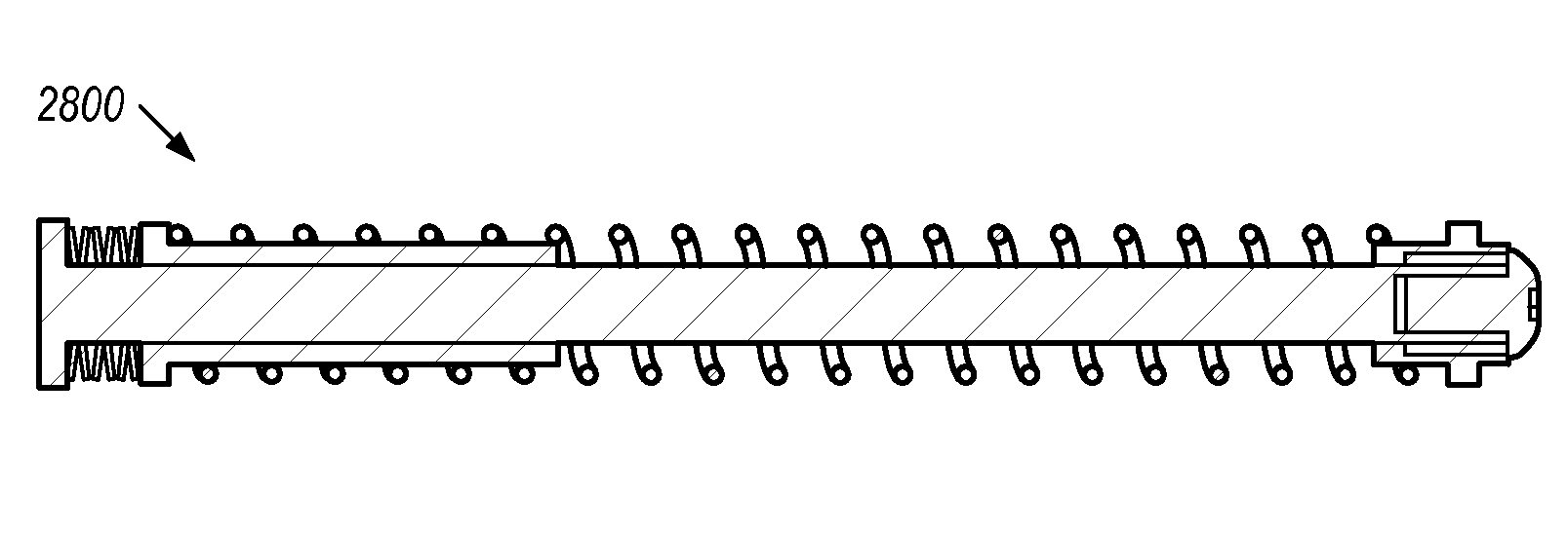
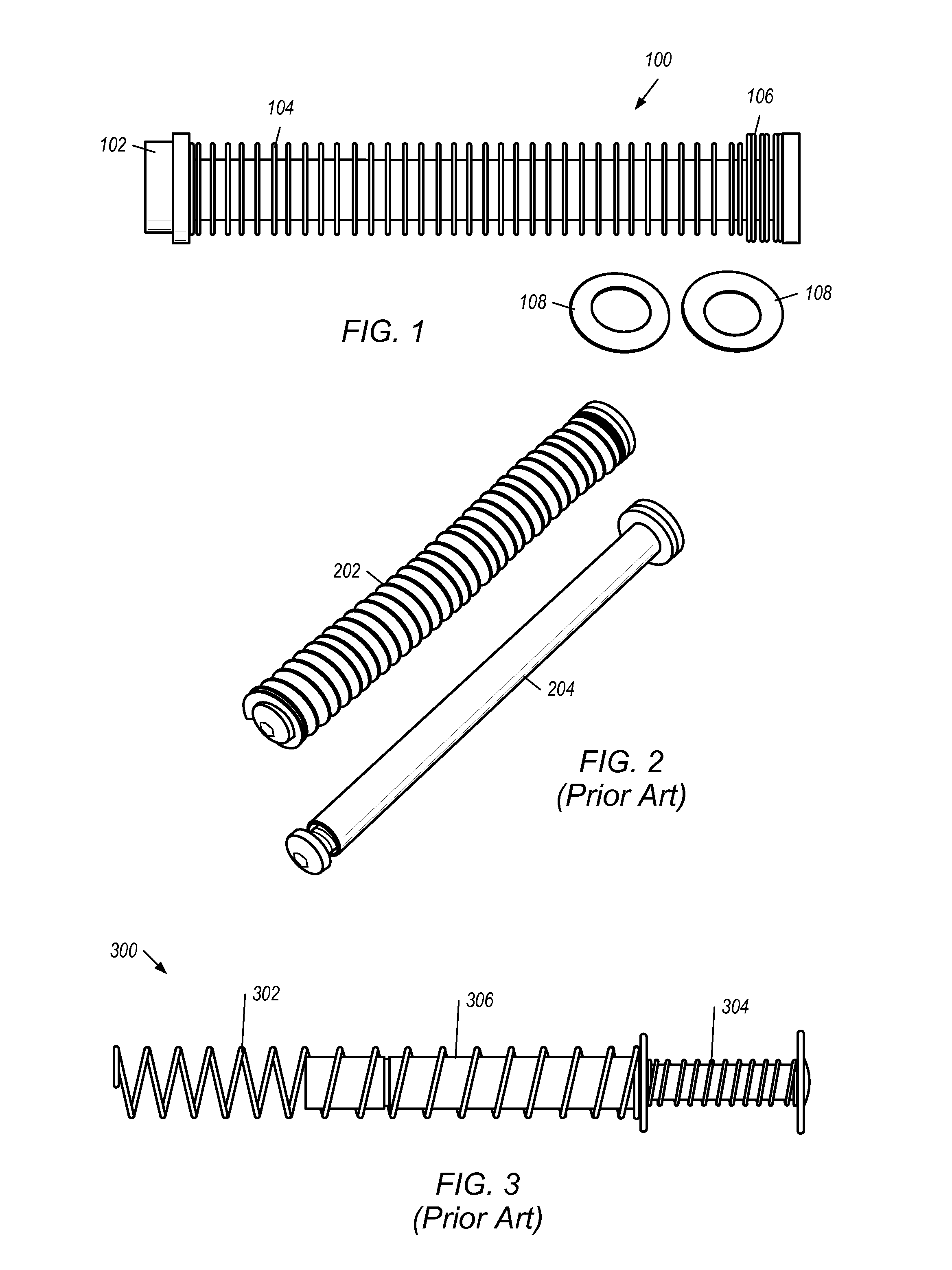
[0059]In one set of embodiments, a progressive recoil action system may be designed and used in semiautomatic handguns to allow for the use of lighter springs suitable for basic operation of light loads, and higher energy density springs that provide a “rebound” effect to absorb any additional force. FIG. 1 shows one example of the basic components of a novel spring assembly 100 that may be used in a novel recoil action system, and includes a guide rod 102 having a front-end stop 110 and a back-end stop 112, a mainspring 104, and a stack 106 of Belleville springs 108 captured between mainspring 104 and back-end stop 112. The spring assembly 100 and configuration of the Belleville springs 108 will be described in further detail below. Overall, as shown in FIG. 1, a high-energy stack of Belleville disc springs may be used to modify the spring recoil assembly for the recoil action system. FIG. 8 illustrates the basic Belleville spring 802, and a side view 820 illustrating the character...


PUM


Abstract

A spring / rod recoil assembly may be improved with Belleville springs arranged in combinations of nested and inverted stacks that absorb recoil impact energy while providing rebound energy to properly load cartridges from the magazine into the chamber. A firearm assembly may include a cylindrical spring, and guide rod—having stops at both ends—lengthwise situated within the cylindrical spring. The assembly may include a Belleville spring stack captured on the guide rod between a back-end stop and the cylindrical spring, with one or more stacks of nested springs and one or more stacks of inverted springs. The spring stack may be arranged to return some of the recoil energy produced during firing of the firearm, and decelerate slide velocities without damage to the firearm. Each spring has a diameter allowing it to fit within a back chamber where at least the back-end of the guide rod and spring are situated.

Description

PRIORITY CLAIM[0001]This application claims benefit of priority of U.S. provisional application Ser. No. 61 / 714,475 titled “Progressive Gun Spring Recoil System with High Energy Rebound”, filed Oct. 16, 2012, which is hereby incorporated by reference in its entirety as though fully and completely set forth herein.BACKGROUND OF THE INVENTION[0002]1. Field of the Invention[0003]This invention relates generally to semiautomatic gun mainspring recoil systems, and more specifically to a recoil spring system with improved lock-up, rebound, and reduced muzzle rise with minimal impact.[0004]2. Description of the Related Art[0005]FIG. 2 is shows a typical semiautomatic gun recoil spring that traditionally uses a guide rod 204 and mainspring 202 with enough force suitable to offset the force of the blowback of the slide, and allow proper cycling of action. If the spring 204 is too light, the slide velocity can reach high enough values to result in an impact on the frame that can cause prematu...

Claims


Application Information

Patent Timeline
Patent Type & Authority Patents(United States)
IPC IPC(8): F41A3/80F41A3/10F41A3/82
CPCF41A3/10F41A3/80F41A3/82F41A3/86
Inventor COFFMAN, II, CHARLES W.
Owner RECOIL REBOUND
Why Eureka
Try Eureka