
Impairment simulation for network communication to enable voice quality degradation estimation

a network communication and impairment simulation technology, applied in the field of impairment simulation, can solve the problems of packet loss, packet delay, packet loss fluctuation, packet error, etc., and achieve the effect of reducing the number of people listening

Inactive Publication Date: 2015-01-27
ANRITSU CORP
View PDF9 Cites 30 Cited by
  • Summary
  • Abstract
  • Description
  • Claims
  • Application Information

AI Technical Summary

Benefits of technology

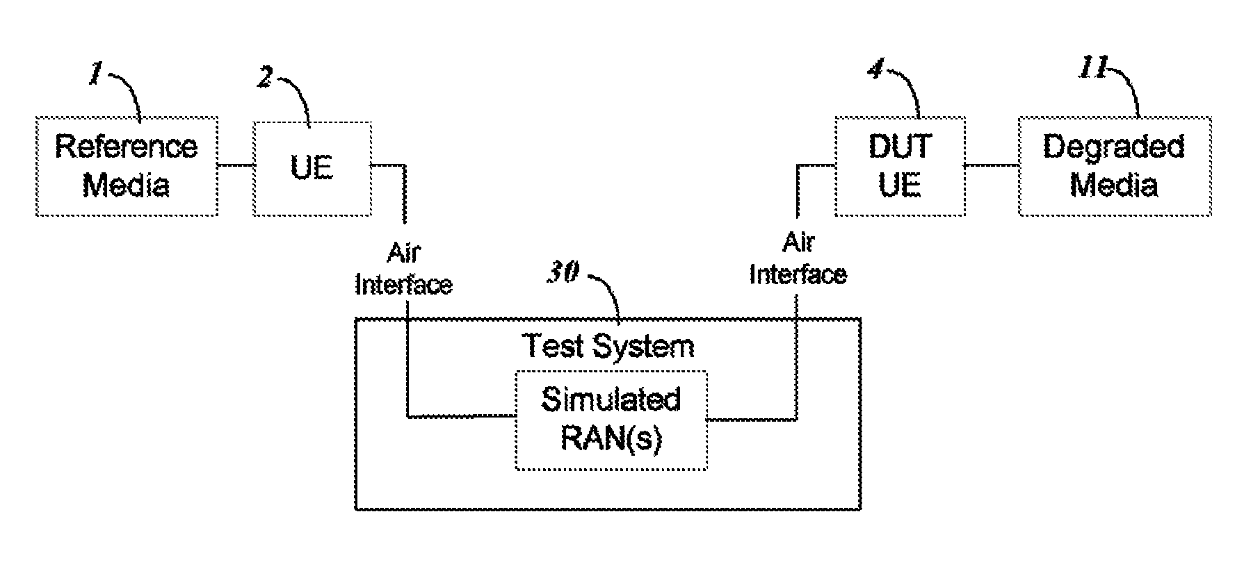
[0014]Embodiments of the invention provide an automated method to estimate a Mean Opinion Score (MOS) for a Device Under Test (DUT) using inexpensive test components. The test system uses a server computer to eliminate the need for faders and other test equipment conventionally used. The server computer manipulates data packets from the reference media file to simulate noise and jitter at a much lower cost than using actual faders. The server computer also uses software to provide a solution for automated assessment of the speech quality as experienced by a user of a wireless telephony system. The server computer provides the automated assessment with software that performs a perceptual objective listening quality assessment by a standardized methodology such as PESQ or POLQA or similar procedure known in the art. The system may assess the media quality for media transmitted over the air interface in the downlink direction (towards the DUT) and / or transmitted in the uplink direction (from the DUT).
[0015]The test system server can estimate media quality for voice and for video media. The computer creates a simulated reference speech or video sample that is extracted as a reference media file and converted into a Voice over IP (VoIP) packet stream. Artificial impairments are imposed by the server computer on individual packets in the stream of packets to simulate the impairments that are typical during transmission over one or more wireless Radio Access Network(s) (RANs). The impairments introduced simulate impairments created by the air interfaces 6, 10 or radio frequency (RF) links as well as a wireless connection system 8 that can cause the order of packets received to be delayed or changed so that the order of packets must be changed back upon reception by a target peer media device DUT to maintain the correlation between consecutive packets and prevent voice signal disruption. The impairments introduced can also simulate a dropping of a first individual packet that causes a delay in transmission of a second individual packet, a condition that causes packets to bunch up which will affect voice quality. The system can introduce the impairments using a simulated source peer media device for the UE 2, enabling simulation of transmission through two separate RANs by two parties communicating using separate mobile devices (an end-to-end test solution) with a single cell phone.
[0016]In the test system, an operator can vary the parameters for the impairments in the first and second RANs and investigate its effect on the DUT and the media quality. This allows for rapid characterization of the DUT, or, conversely, an efficient way to optimize the configuration of the RANs.
[0020]The test solution of embodiments of the present invention can, thus, provide the following features: (1) an independent simulation of a source RAN, target RAN and the network that connects the RANs; (2) a solution that manipulates data packets to simulate losses, errors, noise and jitter by introducing impairments while controlling a correlation between the impairments imposed on consecutive packets; and (3) a solution that enables simultaneous estimation of an end-to-end MOS and the contribution to the total MOS from a single DUT.

Problems solved by technology

Gathering people to listen is time consuming and costly.
The components making up a RAN (e.g. the source UE and base station) and the air interface that connects them (e.g. the LTE air interface) introduces impairments such as packet losses, packet delays, fluctuations in the packet losses (jitter) and packet errors (frame errors).
This causes precisely controlled losses, delays, jitter and frame errors on the air interfaces.

Method used


Image

  • Impairment simulation for network communication to enable voice quality degradation estimation
  • Impairment simulation for network communication to enable voice quality degradation estimation
  • Impairment simulation for network communication to enable voice quality degradation estimation

Examples


Embodiment Construction

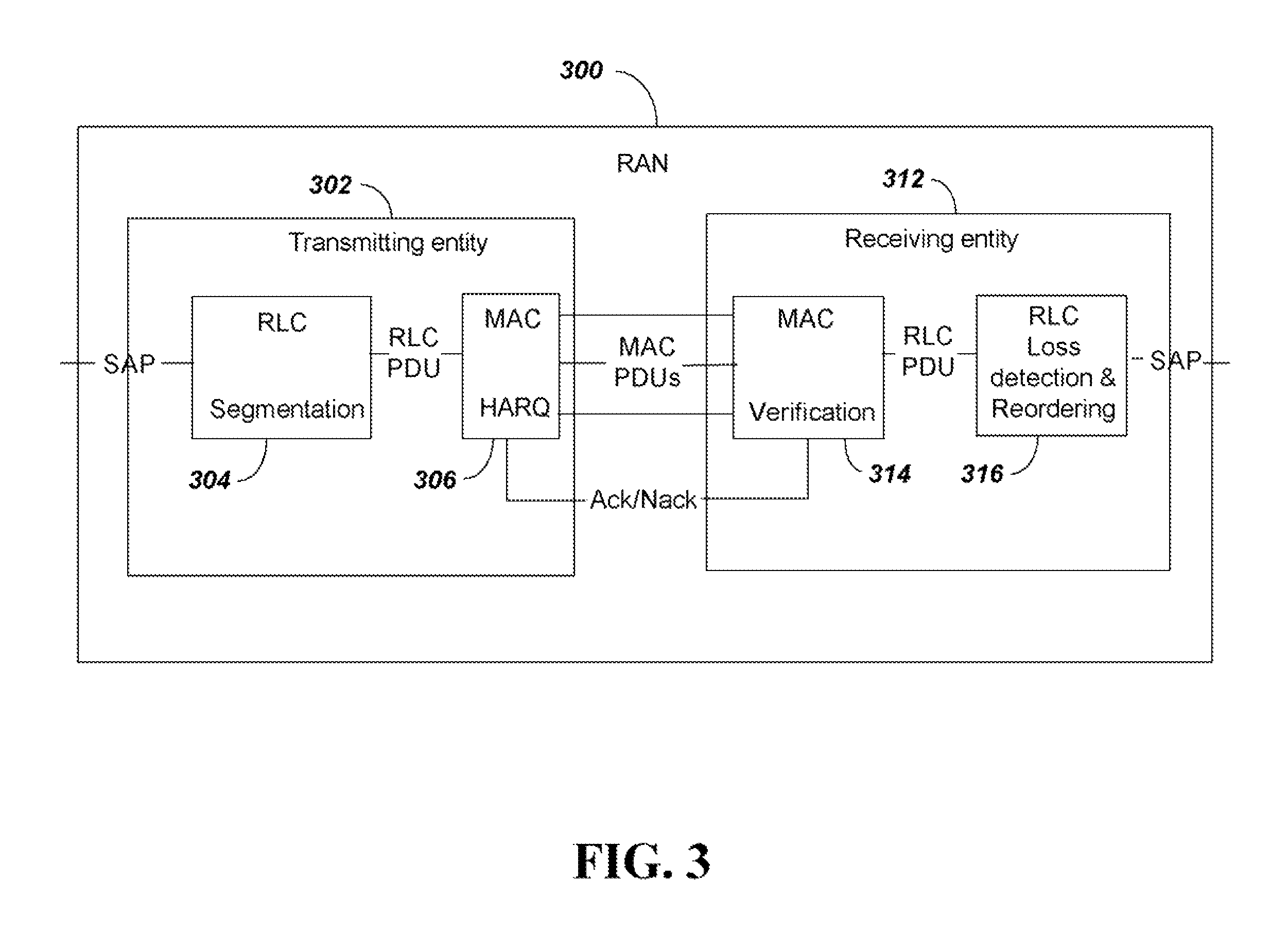
[0039]FIG. 3 shows components of a RAN 300 to illustrate signals that are transmitted and received over a typical LTE network. The system of FIG. 3 will enable a subsequent explanation of how a server computer in the test system according to the present invention can manipulate the signals to simulate noise and jitter. FIG. 3 illustrates the operation of various protocol layers that impact voice quality in an LTE RAN. For simplicity it only shows the Radio Link Control (RLC) layer and the Media Access Control (MAC) protocol layers.

[0040]For a source RAN, the transmitting entity is the source UE and the receiving entity is the base station. In the target system those roles are reversed. Only operation in Unacknowledged RLC Mode (UM) will be discussed, since that mode is typically used for voice and video. Details of the MAC and RLC operation can be found in 3GPP Technical Specification (TS) 36.321 and TS 36.322 respectively.

[0041]The transmitting entity 302 receives data at a Server ...


PUM


Abstract

An automated method for testing audio signal quality of cell phone transmissions provides a Mean Opinion Score (MOS) output using inexpensive test components. The test system uses a server computer to eliminate the need for expensive faders used in a bench test system. The server computer manipulates data packets from the reference media file to simulate impairments, including losses, errors, noise and jitter, at a much lower cost than using actual faders. Transmission through two separate radio access networks RANs is provided to simulate two parties communicating using separate mobile devices (an end-to-end test solution) with a single cell phone.

Description

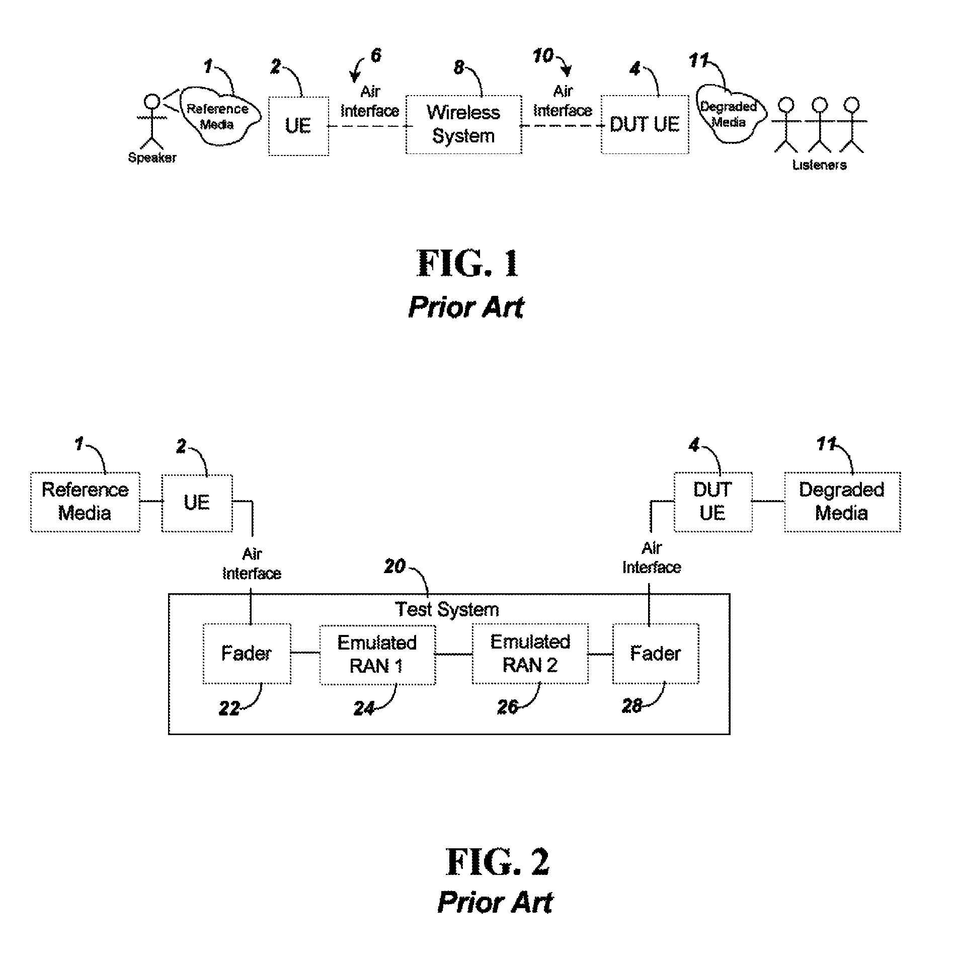
BACKGROUND[0001]1. Technical Field[0002]The present invention relates to a test system for simulating impairments, including losses, errors, noise and jitter, in a network wireless communication signal to enable estimation of the resulting degradation in voice or video quality.[0003]2. Related Art[0004]Operators need to ensure that their systems provide excellent multimedia quality. Every time a new handset is introduced, it should be tested to make sure it produces clear audio and video under ideal and under degraded coverage conditions.[0005]FIG. 1 illustrates the classic test system to measure media quality in a wireless system. Typically the media quality is measured or estimated for voice media or for video media. As shown, the system includes two User Equipment (UE) devices 2 and 4 which enable telephony type voice communications over a wireless link. The devices 2 and 4 can be cellular mobile phones. The UE 2 is used by a speaker to provide a voice reference media 1 that is c...

Claims


Application Information

Patent Timeline
Patent Type & Authority Patents(United States)
IPC IPC(8): H04L12/26
CPCH04W24/06H04L41/145H04L43/0823
Inventor DORENBOSCH, JHEROEN PIETERCOLLINS, ZACHRY SHAY
Owner ANRITSU CORP
Learn More