
System for magnetorheological finishing of a substrate

a technology of magnetorheological polishing and substrate, which is applied in the direction of magnetic bodies, lapping machines, manufacturing tools, etc., can solve the problems of difficult cleaning and maintenance of the system, inability to control the removal rate by varying the strength of the magnetic field, and inability to finish concave surfaces, etc., to achieve the effect of reducing maintenance costs and electrical power consumption

Active Publication Date: 2015-02-03
QED TECH INT LLC
View PDF9 Cites 1 Cited by
  • Summary
  • Abstract
  • Description
  • Claims
  • Application Information

AI Technical Summary

Benefits of technology

Enables the finishing of steep concave substrates with smaller-radius wheels, providing unencumbered space for substrate extension and allowing variable magnetic field control for improved finishing precision and reduced operational costs.

Problems solved by technology

A serious shortcoming of the '066 system is the inability to finish concave surfaces because of the cylindrical carrier wheel surface.
A further shortcoming is that a permanent magnet provides only one value of magnetic field, and thus control of removal rate by varying the strength of the magnetic field is not possible.
A still further shortcoming is that a permanent magnetic field makes difficult the cleaning and maintaining of the system for the fluid changeover.
A shortcoming of the '102 system is that the increased size of an electromagnet (in comparison to an equivalent-strength permanent magnet) imposes limitations on the minimum size of the spherical wheel, and thus limits the smallest radius of curvature of concave substrates to be finished.

Method used


Image

  • System for magnetorheological finishing of a substrate
  • System for magnetorheological finishing of a substrate
  • System for magnetorheological finishing of a substrate

Examples


Embodiment Construction

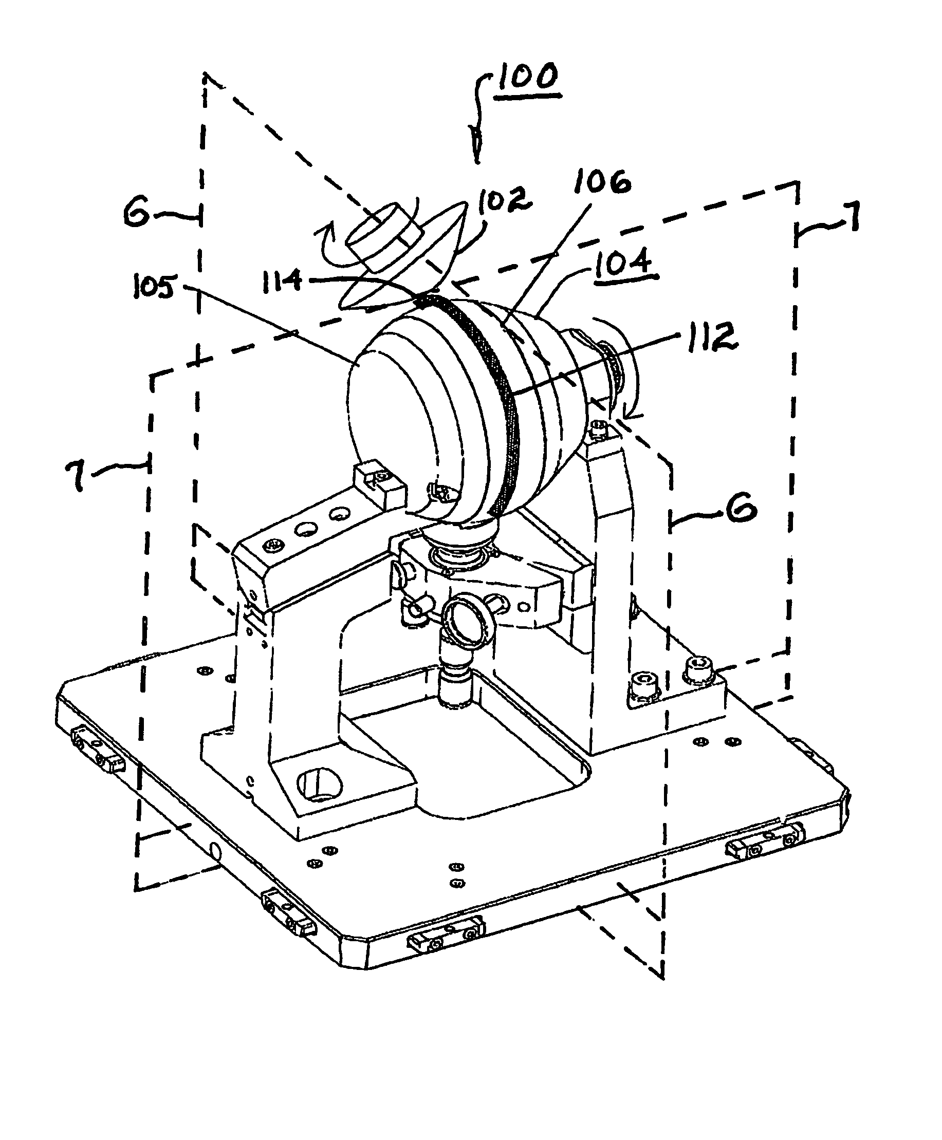
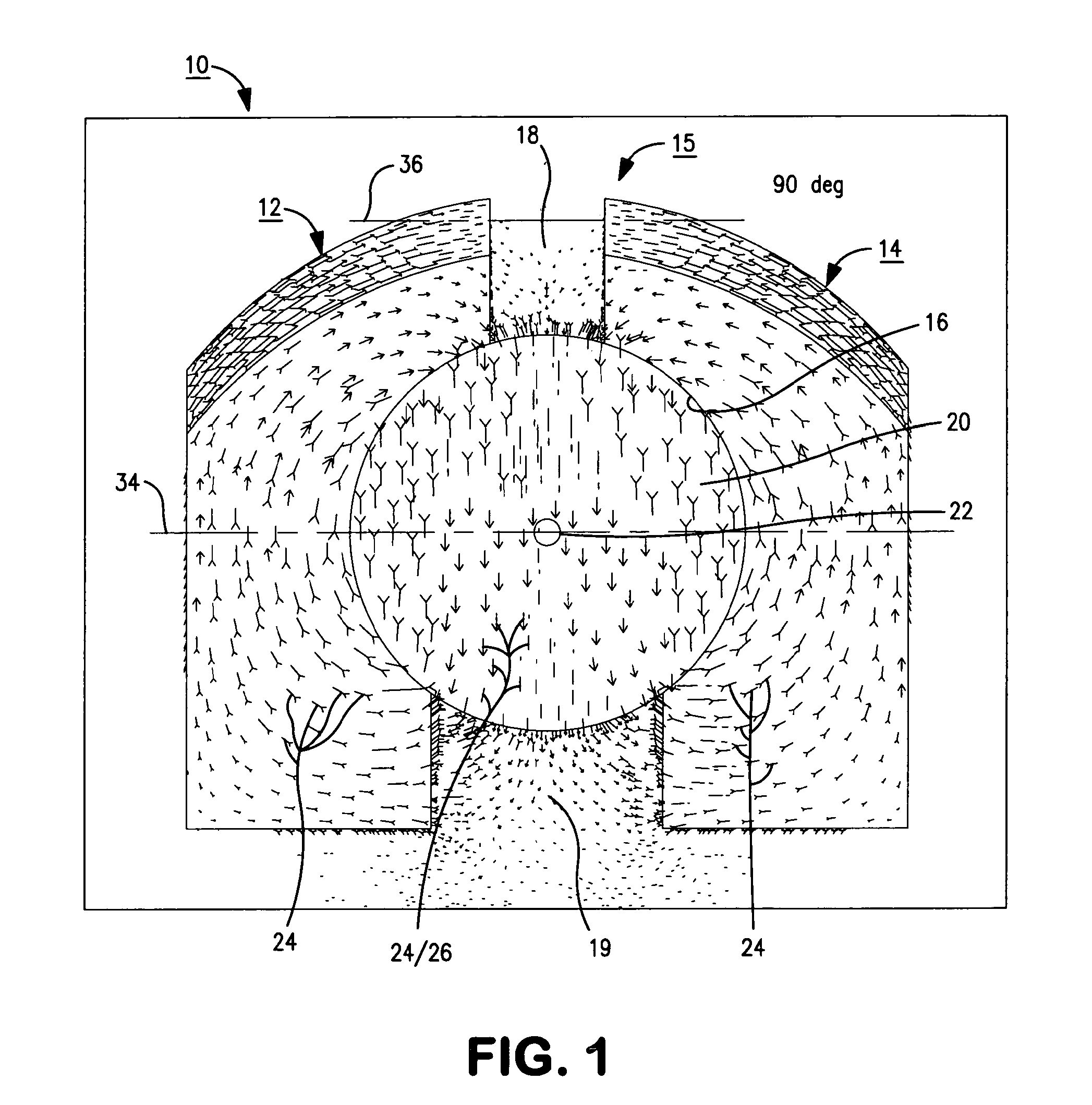
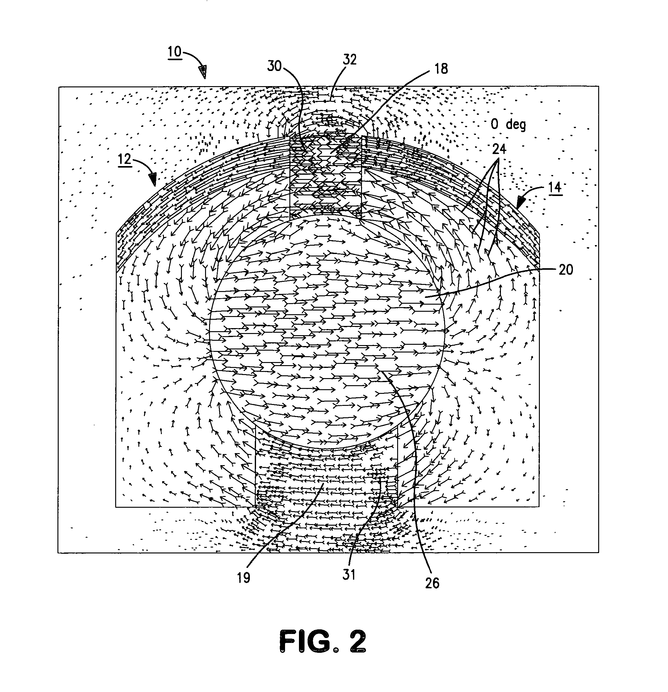
[0034]Referring to FIG. 1, a variable-field permanent magnet system 10 in accordance with the present invention comprises two poles 12, 14 made of a magnetically soft material, preferably iron, defining a magnetic body 15 with a cylindrical cavity 16 bored through the center. The body halves 12, 14 are joined together by a non-magnetic material such as brass, aluminum, or plastic, defining a primary magnetic gap 18 and a secondary magnetic gap 19 between halves 12, 14. A cylindrical permanent magnet 20 magnetized normal to the cylinder axis 22 is inserted into cavity 16 and an actuator 110 (shown in FIGS. 5-7) is attached to allow rotation of magnet 20 about axis 22. Such a magnet is available from, for example, Dexter Magnetic Technologies, Elk Grove Village, Ill., USA. The act of rotation changes the distribution of the magnetic flux 24 in the magnetic circuit. When the field 26 of the permanent magnet is directed vertically as shown in FIG. 1, flux 24 is evenly distributed betwee...


PUM

PropertyMeasurementUnit
angleaaaaaaaaaa
magnetically softaaaaaaaaaa
magnetic field intensityaaaaaaaaaa

Abstract

A system for magnetorheological finishing of a substrate. A spherical wheel meant for carrying a magnetorheological finishing fluid houses a variable-field permanent magnet system having north and south iron pole pieces separated by primary and secondary gaps with a cylindrical cavity bored through the center. A cylindrical permanent magnet magnetized normal to the cylinder axis is rotatably disposed in the cavity. An actuator allows rotation of the permanent magnet to any angle, which rotation changes the distribution of flux in the magnetic circuit through the pole pieces. Thus, one can control field intensity in the gaps by positioning the permanent magnet at whatever angle provides the required field strength. Because the field also passes above the pole pieces, defining a fringing field outside the wheel surface, the variable field extends through a layer of MR fluid on the wheel, thus varying the stiffness of the MR fluid as may be desired for finishing control.

Description

CROSS-REFERENCE TO RELATED APPLICATIONS[0001]This application claims the benefit of U.S. Provisional Application for Patent Ser. No. 61 / 158,021, filed on Mar. 6, 2009, which is incorporated herein by reference.TECHNICAL FIELD[0002]The present invention relates to systems for slurry-based abrasive finishing and polishing of substrates, and particularly, to such systems employing magnetorheological fluids and magnets adjacent to a spherical carrier wheel for magnetically stiffening the fluid in a work zone on the wheel; more particularly, to such systems wherein the stiffening magnets are disposed within the carrier wheel itself; and most particularly, to an improved system wherein the stiffening magnet is a variable-field permanent magnet assembly.BACKGROUND OF THE INVENTION[0003]Use of magnetically-stiffened magnetorheological fluids (MRF) for abrasive finishing and polishing of substrates is well known. Such fluids, containing magnetically-soft abrasive particles dispersed in a liq...

Claims


Application Information

Patent Timeline
Patent Type & Authority Patents(United States)
IPC IPC(8): B24B49/00B24B51/00B24B1/00B24B31/10B24B31/112
CPCB24B1/005B24B31/102B24B31/112B24B57/02B24B31/00B24B37/00
Inventor KORDONSKI, WILLIAM
Owner QED TECH INT LLC
Learn More