Semiconductor device comprising a buried capacitor formed in the contact level

a capacitor and contact level technology, applied in the field of capacitors, can solve the problems of increasing the dynamic power consumption of individual transistors, affecting reducing the efficiency of capacitor electrodes, so as to achieve the effect of efficient adjustment of the desired capacitance, superior integrity of capacitor electrodes, and efficient cover of capacitor electrodes

Active Publication Date: 2015-02-03
GLOBALFOUNDRIES US INC
View PDF9 Cites 2 Cited by
  • Summary
  • Abstract
  • Description
  • Claims
  • Application Information

AI Technical Summary

Benefits of technology

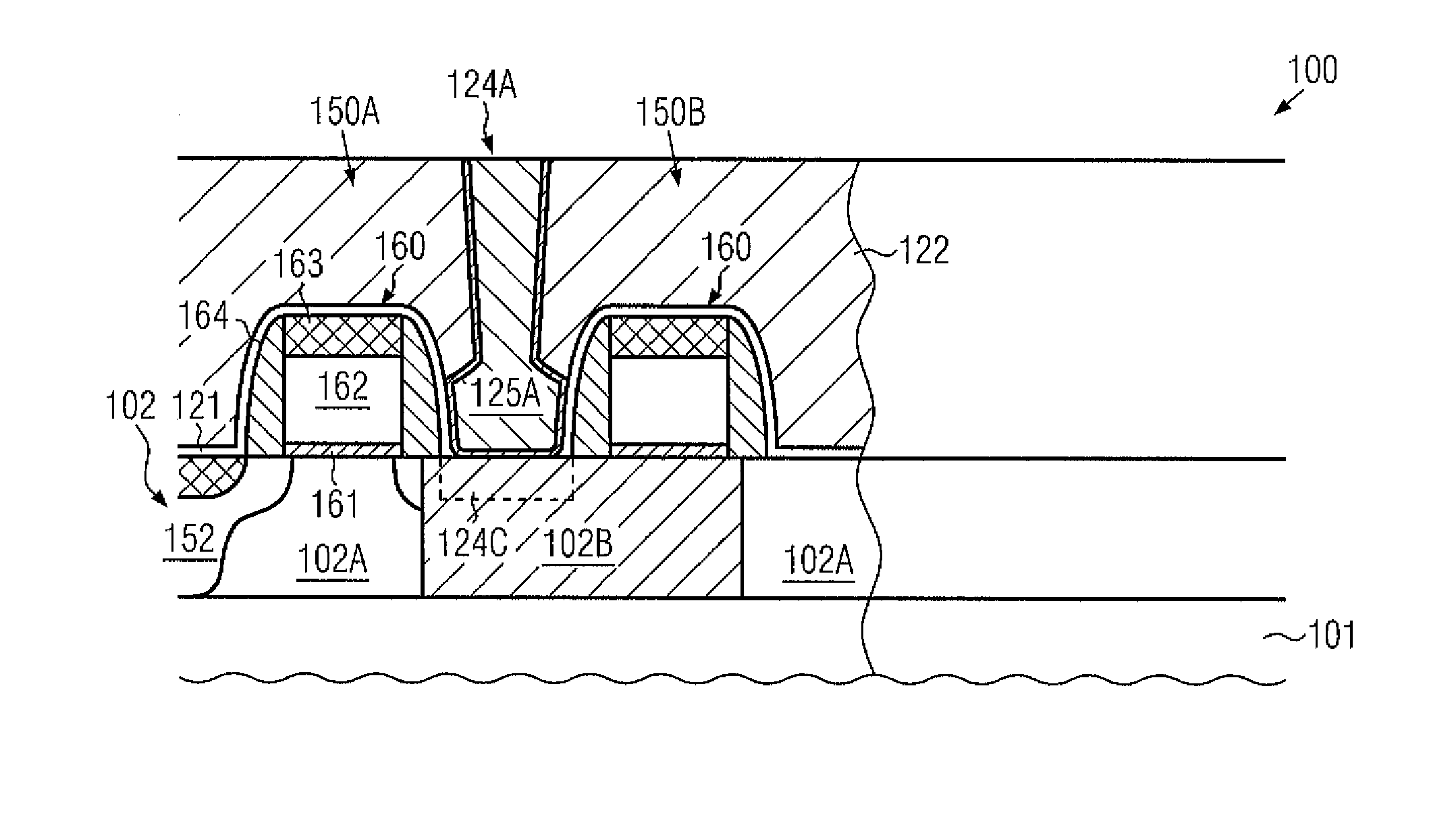
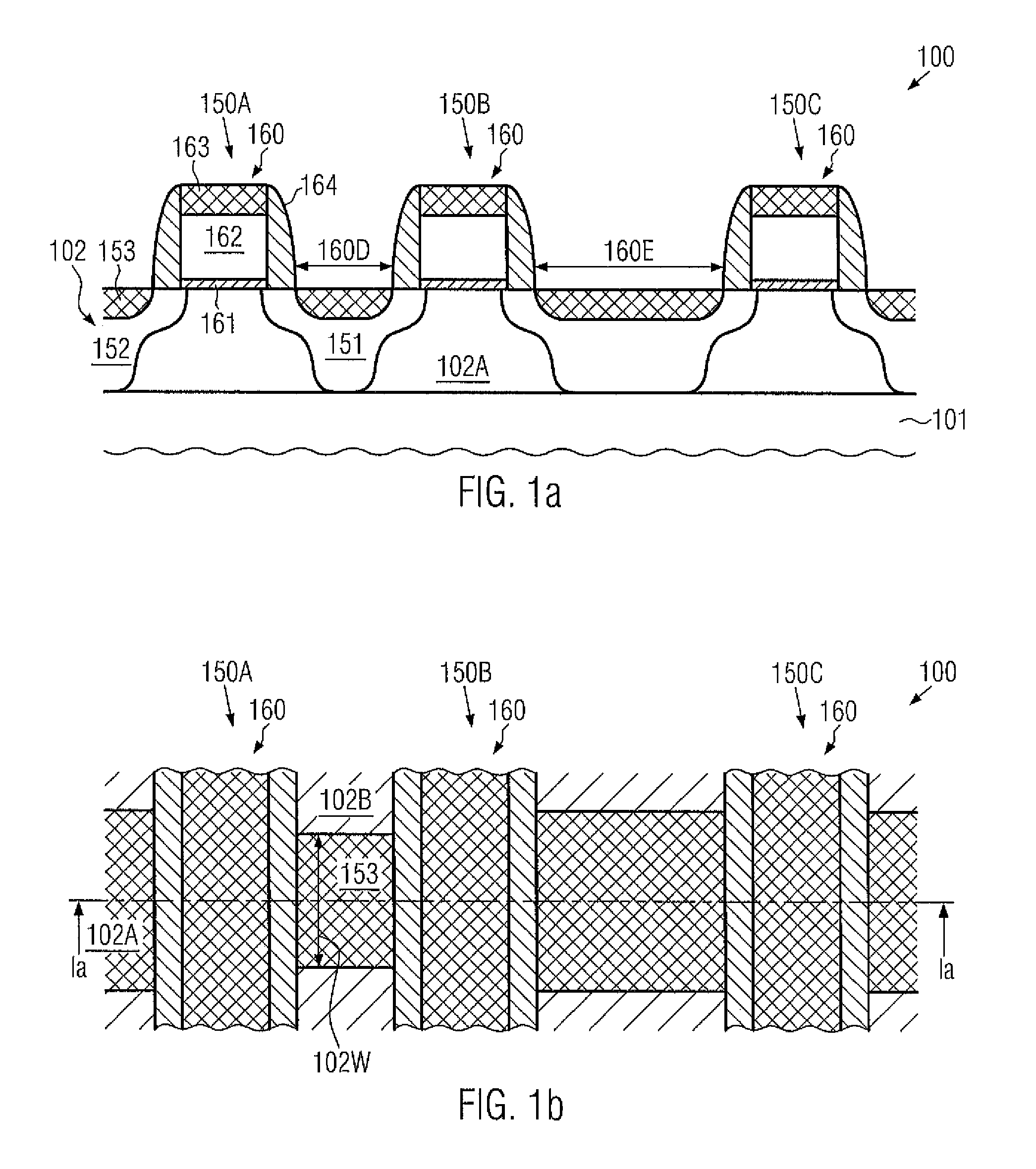
[0012]Generally, the present disclosure provides semiconductor devices and manufacturing techniques in which capacitive structures or capacitors may be efficiently formed in the contact level of semiconductor devices, i.e., in the device level that represents an interface between the semiconductor-based circuit elements, such as the transistors, and a metallization system. The capacitors may have one capacitor electrode formed in the active semiconductor region, which may also act as a drain region or a source region of one or more transistors that may be formed in and above the active semiconductor region. Consequently, a very space-efficient configuration may be obtained since any additional interconnect structures for connecting to the electrode provided in the active semiconductor region may be avoided, since this electrode may be directly connected to a transistor. On the other hand, the second capacitor electrode may be provided in the form of a buried conductive electrode, which may be formed in the dielectric material of the contact level, which may thus efficiently cover the capacitor electrode and thus provide superior integrity thereof. Furthermore, any appropriate dielectric material, such as conventional dielectrics in the form of silicon nitride, silicon dioxide and the like, or high-k dielectric materials, i.e., dielectric materials having a dielectric constant of 10.0 or higher, or combinations of conventional dielectric materials and high-k dielectric materials may be formed between the buried capacitor electrode and the active semiconductor region, at least in an area corresponding to the capacitor, thereby enabling an efficient adjustment of the desired capacitance by selecting an appropriate material composition and layer thickness for a given geometric configuration of the semiconductor device. Hence, due to the compact configuration of the capacitor, high density memory areas, such as dynamic RAM areas, may be provided, wherein the capacitor, directly connected to a transistor, may provide the large storage capability.
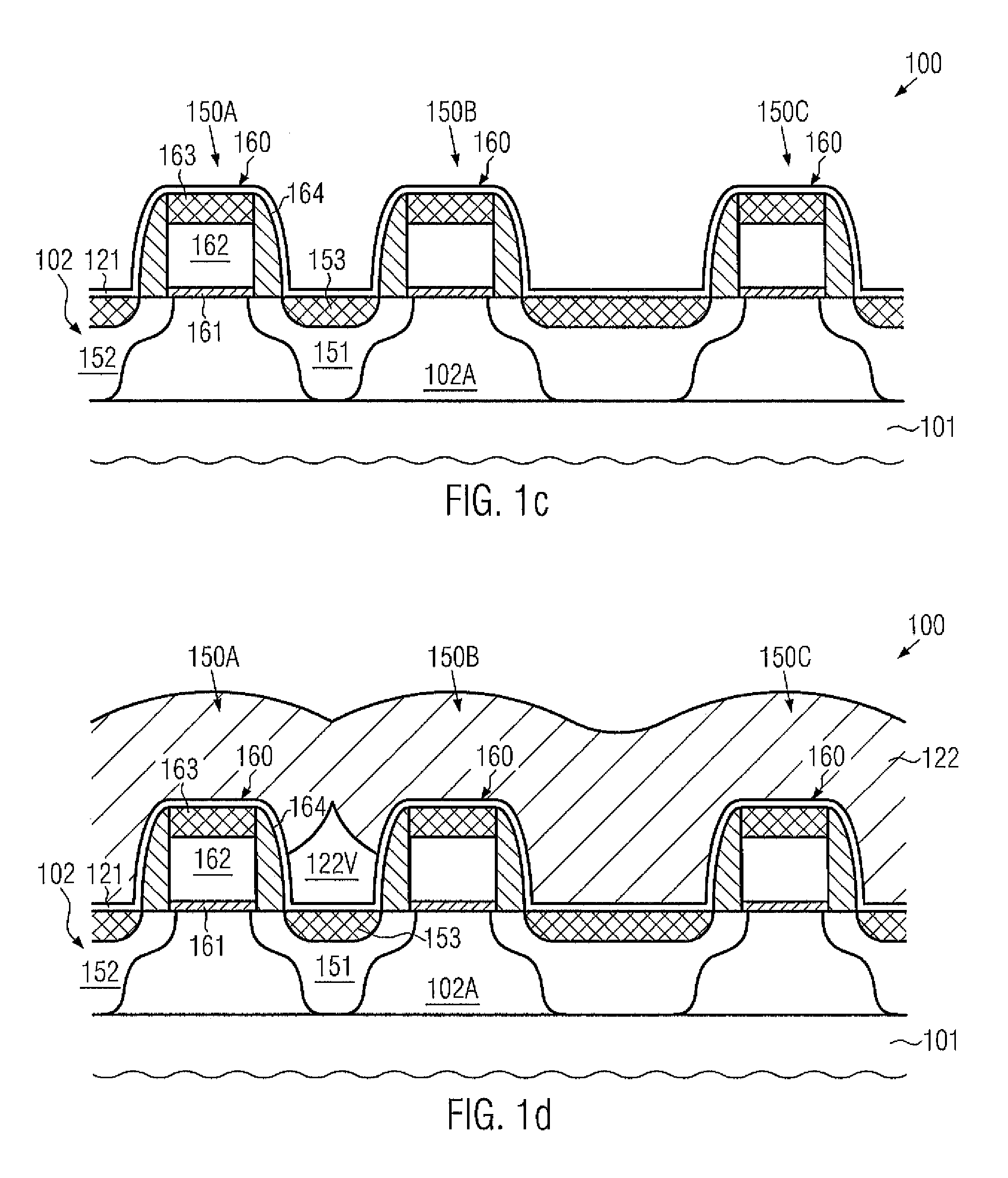
[0013]The buried capacitor electrode may be formed by providing a void in the interlayer dielectric material upon depositing the dielectric material, wherein the void, which may extend along the entire width of the underlying active region, may be efficiently filled with a conductive material upon forming contact elements. In this manner, a high degree of compatibility with conventional process strategies may be achieved.

Problems solved by technology

The reduction in size commonly brings about an increased switching speed, thereby enhancing signal processing performance, while, however, increasing dynamic power consumption of the individual transistors.
For this reason, highly complex circuits have been developed, which may include different types of circuits, such as analog circuits, digital circuits and the like, thereby providing entire systems on a single chip (SoC).
While the planar architecture may require significant silicon area, the vertical arrangement may necessitate complex patterning regimes for forming the trenches of the capacitors.
Consequently, also in this case, additional process modules may have to be implemented into the overall process flow, which may thus contribute to additional process complexity.
As pointed out above, although a space efficient configuration may be achieved, nevertheless, extremely complicated processes, in particular for patterning the deep trenches for the capacitors in the semiconductor substrate, may be required, which may also be different for bulk devices and SOI devices, so that, in total, significant process-related variations may be introduced in complex semiconductor devices.
On the other hand, providing the capacitors in the metallization system may provide additional interconnect complexity combined with sophisticated process modules for forming the capacitors independently from the regular metal interconnect structures.

Method used


Image

  • Semiconductor device comprising a buried capacitor formed in the contact level
  • Semiconductor device comprising a buried capacitor formed in the contact level
  • Semiconductor device comprising a buried capacitor formed in the contact level

Examples


Embodiment Construction

[0026]Various illustrative embodiments of the invention are described below. In the interest of clarity, not all features of an actual implementation are described in this specification. It will of course be appreciated that in the development of any such actual embodiment, numerous implementation-specific decisions must be made to achieve the developers' specific goals, such as compliance with system-related and business-related constraints, which will vary from one implementation to another. Moreover, it will be appreciated that such a development effort might be complex and time-consuming, but would nevertheless be a routine undertaking for those of ordinary skill in the art having the benefit of this disclosure.

[0027]The present subject matter will now be described with reference to the attached figures. Various structures, systems and devices are schematically depicted in the drawings for purposes of explanation only and so as to not obscure the present disclosure with details ...


PUM


Abstract

In a semiconductor device, capacitors may be formed so as to be in direct contact with a transistor by using a shared transistor region, such as a drain region or a source region of closely spaced transistors, as one capacitor electrode, while the other capacitor electrode is provided in the form of a buried electrode in the dielectric material of the contact level. To this end, dielectric material may be deposited so as to reliably form a void, wherein, at any appropriate manufacturing stage, a capacitor dielectric material may be provided so as to separate the capacitor electrodes.

Description

BACKGROUND OF THE INVENTION[0001]1. Field of the Invention[0002]The present disclosure generally relates to the field of fabricating integrated circuits, and, more particularly, to capacitors, such as capacitors for dynamic random access memories (DRAM), decoupling capacitors and the like.[0003]2. Description of the Related Art[0004]In modern integrated circuits, a very high number of individual circuit elements, such as field effect transistors in the form of CMOS, NMOS, PMOS elements, resistors, capacitors and the like, are formed on a single chip area. Typically, feature sizes of these circuit elements are reduced with the introduction of every new circuit generation, to provide currently available integrated circuits with high performance in terms of speed and / or power consumption. A reduction in size of transistors is an important aspect in steadily improving device performance of complex integrated circuits, such as CPUs. The reduction in size commonly brings about an increase...

Claims


Application Information

Patent Timeline
Patent Type & Authority Patents(United States)
IPC IPC(8): H01L21/8242H01L23/522H01L27/06
CPCH01L27/0629H01L23/5223H01L2924/0002
Inventor CHUMAKOV, DMYTROHERTZSCH, TINO
Owner GLOBALFOUNDRIES US INC
Why Eureka
Try Eureka