
Gasifier having integrated fuel cell power generation system

a fuel cell and power generation system technology, applied in the direction of combustible gas production, physical/chemical process catalysts, bulk chemical production, etc., can solve the problem of considerable energy consumption of heat sources, and achieve the effect of facilitating direct electricity production

Active Publication Date: 2015-03-03
THERMOCHEM RECOVERY INT
View PDF30 Cites 24 Cited by
  • Summary
  • Abstract
  • Description
  • Claims
  • Application Information

AI Technical Summary

Benefits of technology

The invention is a system and method for converting carbonaceous materials into a product gas and power simultaneously using a gasifier and fuel cell elements. The gasifier is designed to receive a feedstock of carbonaceous material and produce a product gas by gasification. The fuel cell elements are designed to conduct an exothermic reaction and provide heat to gasify the carbonaceous material. The system includes a reaction vessel with a gasifier chamber and multiple fuel cell elements protruding into the gasifier chamber. The fuel cell elements are in the form of elongated tubes with an outer anode, inner cathode, and ceramic electrode between them. The system also includes an oxidant manifold and a spent oxidant plenum for the removal of N2 or O2 and other gases that were not consumed by the fuel cell elements. The system can be integrated with thermochemical, electrochemical, and catalytic processes to create a push-pull or source-sink reaction environment for direct production of electricity from carbonaceous materials.

Problems solved by technology

The key performance targets are conversion, yield, selectivity and activity and the challenge is to maintain performance with negligible or minimal loss of activity.
In general, such heat sources consume considerable energy.

Method used


Image

  • Gasifier having integrated fuel cell power generation system
  • Gasifier having integrated fuel cell power generation system

Examples


Embodiment Construction

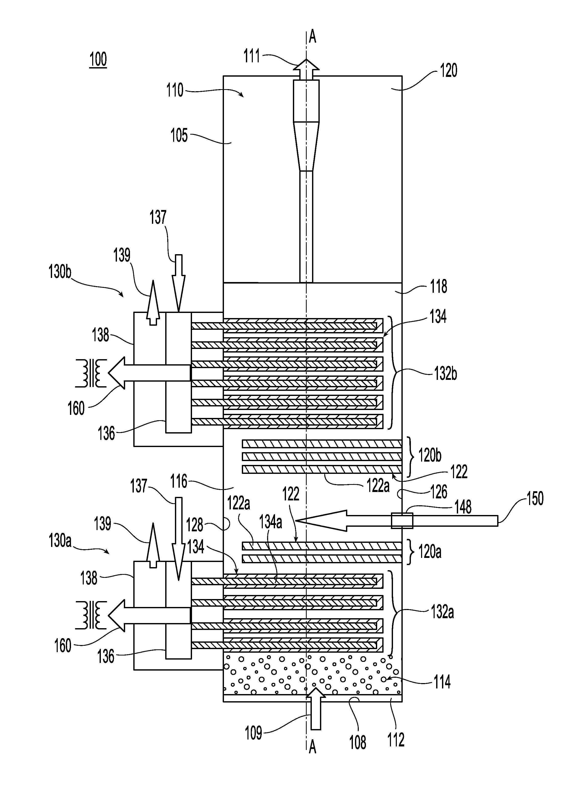
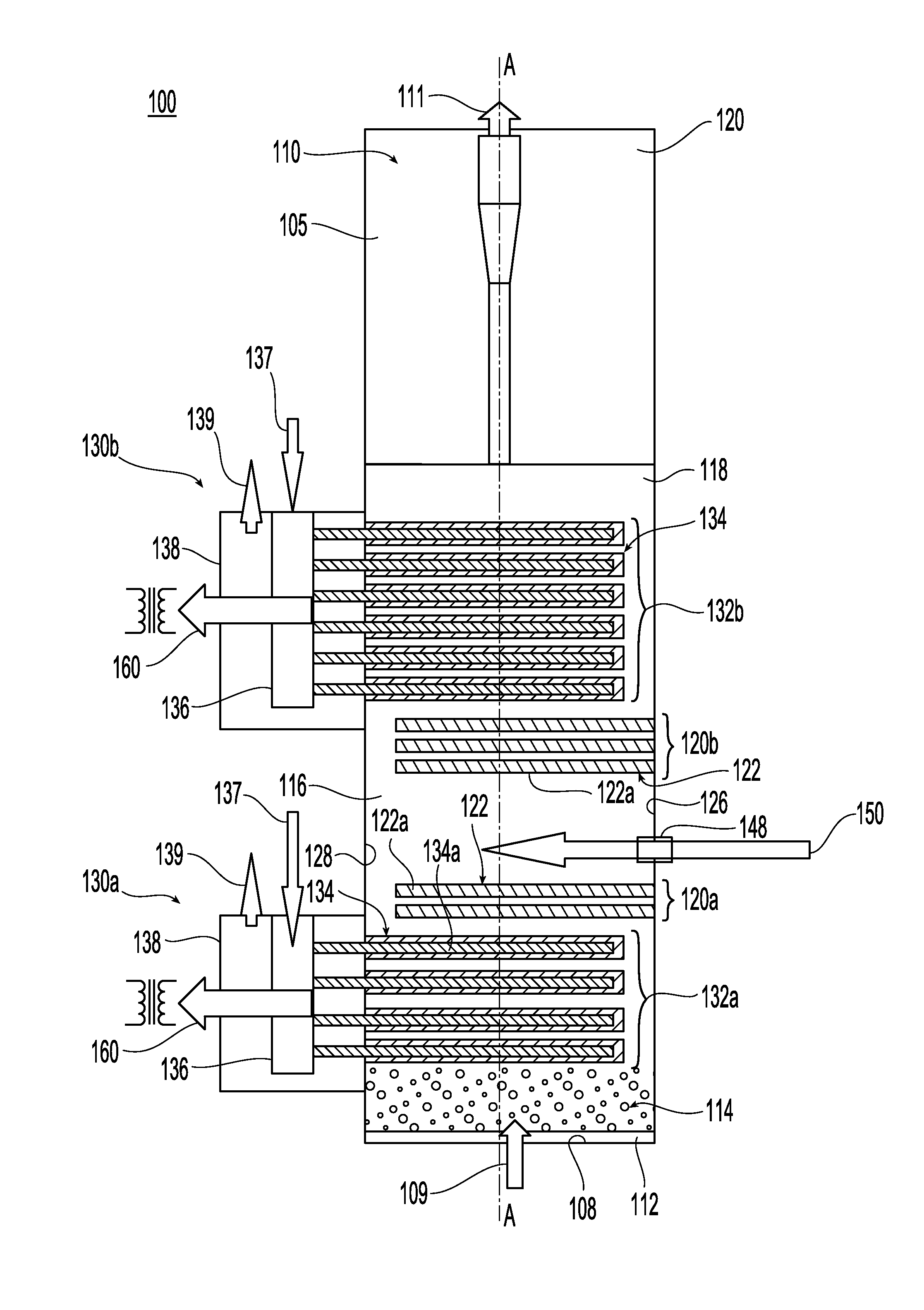
[0026]FIG. 1 shows an integrated carbonaceous material to power generation system 100 in accordance with one embodiment of the present invention. The system 100 includes a reaction vessel 105 comprising a gasifier chamber 110 having a longitudinal axis A defining a vertical direction. In some embodiments, the gasifier chamber 110 may be in the form of a steam reformer, of a sort well-known to those skilled in the art.

[0027]A distributor 112 is provided at the base 108 of the chamber 110 to facilitate entry of the fluidization medium 109, which may include such items as steam, air, CO2, O2, etc. Above the distributor, the gasifier 110 has a plurality of zones including an enhanced char conversion zone 114 proximate the chamber base, a drying and devolatilization zone 116 above the enhanced char conversion zone 114, and a dense fluid bed zone 118 above the drying and devolatilization zone 116. Above the dense fluid bed zone 118 is a freeboard area 120 which occupies the upper portion ...


PUM

PropertyMeasurementUnit
sizeaaaaaaaaaa
sizeaaaaaaaaaa
sizeaaaaaaaaaa

Abstract

A direct carbonaceous material to power generation system integrates one or more solid oxide fuel cells (SOFC) into a fluidized bed gasifier. The fuel cell anode is in direct contact with bed material so that the H2 and CO generated in the bed are oxidized to H2O and CO2 to create a push-pull or source-sink reaction environment. The SOFC is exothermic and supplies heat within a reaction chamber of the gasifier where the fluidized bed conducts an endothermic reaction. The products from the anode are the reactants for the reformer and vice versa. A lower bed in the reaction chamber may comprise engineered multi-function material which may incorporate one or more catalysts and reactant adsorbent sites to facilitate excellent heat and mass transfer and fluidization dynamics in fluidized beds. The catalyst is capable of cracking tars and reforming hydrocarbons.

Description

RELATED APPLICATIONS[0001]This is a Continuation of International Patent Application No. PCT / US2010 / 037127, which was filed Jun. 2, 2010 and published as WO 2010 / 141629A1 on Dec. 9, 2010, and which claims priority to U.S. Provisional Application No. 61 / 183,401, filed 2 Jun. 2009. The contents of the aforementioned applications are incorporated by reference in their entirety.FIELD OF THE INVENTION[0002]The present invention is directed to a system and method for converting a carbonaceous material into a product gas having an integrated full cell for power generation.BACKGROUND[0003]Gasifiers, such as those employing fluidized beds, have been used to convert carbonaceous materials into a product gas. The objective in gasification is to maximize the conversion of feedstock into syngas i.e., H2 and CO. This requires that either the formation of condensables or tars and light hydrocarbons is minimized or that these are converted in-situ. Many investigators have developed catalysts to cra...

Claims


Application Information

Patent Timeline
Patent Type & Authority Patents(United States)
IPC IPC(8): B01J7/00C01B3/44C10J3/48C10J3/62F02C3/28H01M8/06H01M8/12
CPCF02C3/28H01M8/0631H01M8/0643C10J3/482C01B3/44H01M2008/1293Y02E50/12Y02T50/672C10J3/62C10J2300/1246C10J2300/1276C10J2300/1606C10J2300/1612C10J2300/1646C10J2300/1653C01B2203/0233C01B2203/0283C01B2203/0425C01B2203/066Y02E60/50Y02E20/185Y02E60/525Y02E20/16Y02E20/18Y02P20/52Y02E50/10Y02T50/60Y02P20/129C01B3/36C01B2203/0205C01B2203/025C01B2203/067C01B2203/0844C10J3/463C10J3/726C10J2300/0916C10J2300/0976C10J2300/1215H01M8/0618B01J21/04C01B3/02C01B3/12C01B3/50C01B2203/0465C01B2203/0475C01B2203/062C01B2203/0811C01B2203/085C01B2203/1041C01B2203/1205C10J3/466C10J2300/0909C10J2300/094C10J2300/0959C10J2300/0969C10J2300/123C10K1/02F05D2220/32F05D2220/72
Inventor CHANDRAN, RAVI
Owner THERMOCHEM RECOVERY INT
Learn More