Microphone array

a microphone array and array technology, applied in the field of microphone arrays, can solve the problems of inability to guarantee the perception consistency of the reproduced audio with the actual recording environment, requires significant computational resources and a large number of channels, and is not feasible in a domestic setting. to achieve the effect of reducing cross-talk

Active Publication Date: 2015-03-10
DE SENA ENZO +2
View PDF6 Cites 31 Cited by
  • Summary
  • Abstract
  • Description
  • Claims
  • Application Information

AI Technical Summary

Benefits of technology

[0007]Embodiments of the invention improve upon the prior art array by having more carefully defined directivity functions designed to meet two criteria, being firstly to minimise cross-talk between non-adjacent microphones in the array, and secondly to design the array response such that it approximates stereophonic panning curves that have been shown to provided for good auditory localisation.
[0008]One embodiment therefore provides a microphone array, comprising N microphones, wherein N is greater than or equal to 3. The microphones are substantially equiangularly arranged over a circular arc subtending an angle ε, wherein ε is less than or equal to 2π, with the directional axes of the N microphones facing substantially radially outwards. Each of the N microphones have a substantially common directivity function Γ(θ) defining the directional response of the microphone, wherein θ=0 is the directional axis, and the directivity function Γ(θ) is arranged such that a sound source in acoustical free field is effectively captured by no more than two consecutive microphones in the array. By arranging the directivity function in this manner crosstalk between non-adjacent microphones can be minimised, which has been shown to improve auditory localisation performance.
[0012]In numerical terms, effective capture by more than two microphones is prevented in one embodiment when the directivity function Γ(θ) is further arranged such it is at least 15 dB below the value at the directional axis (θ=0), i.e.
[0015]θ<-ɛNwith the angular separation between the microphones with respect to the origin of the circular arc being ε / N. In this regard, −15 dB is sufficient to prevent any signals captured below this level from contributing to the auditory spatial perception when the signals are reproduced, and hence effectively enforces the cross-talk criterion.
[0016]As discussed, the second criterion that is applied is that the array response should approximate stereophonic panning rules, which have been shown to take into account psycho-acoustic characteristics in providing good auditory localisation. Therefore, according to a second embodiment of the invention there is also provided a microphone array, comprising: N microphones, wherein N is greater than or equal to 3. The microphones are again substantially equiangularly arranged over a circular arc subtending an angle ε, wherein ε is less than or equal to 2π, with the directional axes of the N microphones facing substantially radially outwards, and the N microphones have a substantially common directivity function Γ(θ) defining the directional response of the microphone, wherein θ=0 is the directional axis. In this second embodiment, however, the directivity function Γ(θ) is further arranged such that the array response approximates a stereophonic panning curve for sound sources in directions of incidence θ between adjacent microphones in the array. By so doing, the array response takes into account psycho-acoustic parameters such as inter channel level difference, and inter channel time delay, and a more accurate auditory localisation can be obtained.

Problems solved by technology

While satisfactory listener experience can be achieved most of the time, the perceptual consistency of the reproduced audio with the actual recording environment cannot be guaranteed and the reproduced sound field reflects the choices of the audio engineer rather than the properties of the actual recording venue.
The latter requires significant computational resources and a high number of channels and is thus not feasible in a domestic setting.

Method used


Image

  • Microphone array
  • Microphone array
  • Microphone array

Examples


first embodiment

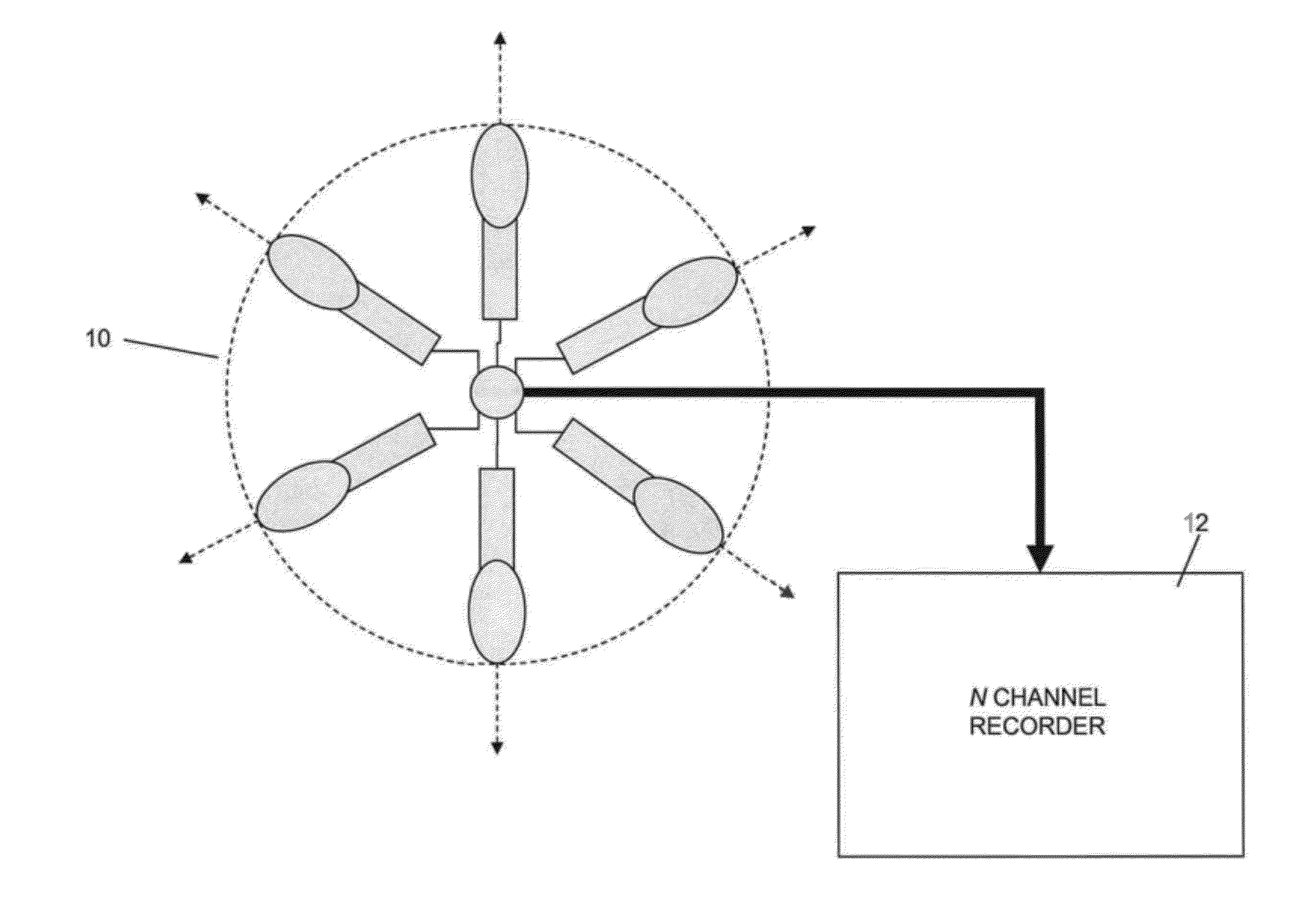
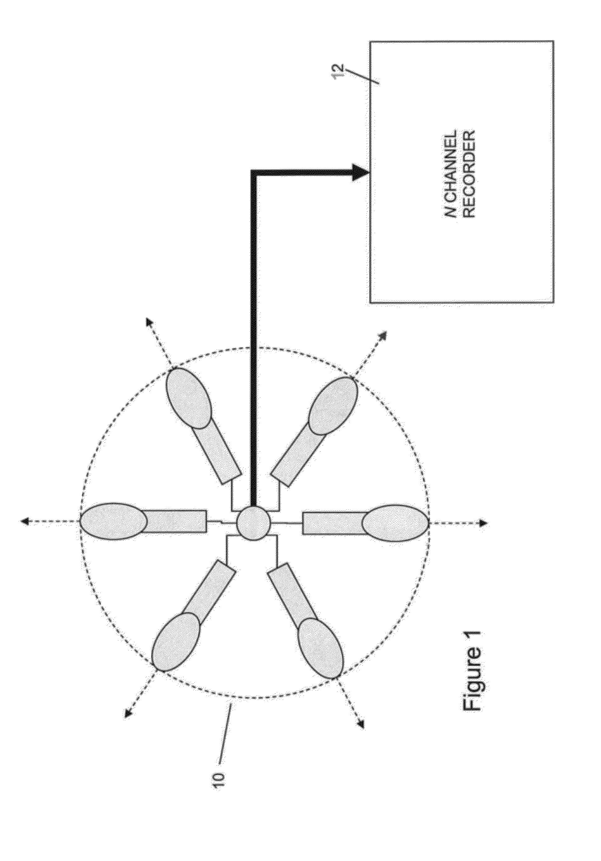
[0077]The aim of the proposed microphone array of the first embodiment is to have at most two loudspeakers active for a single plane wave. For example, if the plane wave is incident from an angle, θ, such that

[0078]2⁢π⁢⁢kN≤θ≤2⁢π⁡(k+1)N

for a circular array, only the loudspeakers k and k+1 should be effectively active. This constraint allows using stereophonic panning laws for designing the common microphone directivity pattern. As described, two rules are employed for this purpose: i) cross-terms, γmk(θ) for non-consecutive microphones, m and k, should be minimized, and ii) directivity function should approximate stereophonic panning laws for directions of incidence between consecutive microphones.

[0079]Assuming a smooth directivity function, Γ(θ), the cross-talk terms can be minimized by designing the directivity function to be zero (or effectively zero) at θ=2πk / N for k≠m. In this way, a sound wave incident from an angle between two consecutive microphones will be reproduced by the...

second embodiment

[0115]In order to actually find the directivity function which meets the cross-talk criterion, and also the time-intensity panning curve as explained above, within the second embodiment the conditions stated above can be imposed analytically as a constrained linear least-squares optimisation problem on the coefficients am in

[0116]Γ⁡(θ)=∑m=0M⁢am⁡[cos⁡(θ)]m,

as follows:

[0117]mina⁢Gm⁢a-ψ22⁢⁢such⁢⁢that⁢⁢{Gt⁢a≤βGz⁢a=0

where

Gm=[cospθm,q] q=0 . . . Qm p=0 . . . M,

Gt=[cospθt,q] q=0 . . . Qt p=0 . . . M,

a=[a0a1 . . . aM]T,

ψ=[g(τ(θm,0)) . . . g(τ(θm,Qm))]T,

β is the maximum allowable crosstalk level between non-consecutive channels, 0≦θm,q≦2π / N, 2π / Nt,q≦π, and θz,q=2πi / N, for i=2, . . . , N−2. Here, θm,q are the angles at which the difference between the directivity function and time-intensity panning gain is minimised, θt,i are the angles at which the cross-talk constraint is applied, and θz,q are the angles at which the directivity function is constrained to be zero.

[0118]FIG. 6 shows the di...


PUM


Abstract

A microphone array, comprising N microphones, wherein N is greater than or equal to 3 is provided. The microphones are substantially equiangularly arranged over a circular arc subtending an angle ε, wherein ε is less than or equal to 2π, with the directional axes of the N microphones facing substantially radially outwards. Each of the N microphones have a substantially common directivity function Γ(θ) defining the directional response of the microphone, wherein θ=0 is the directional axis, and the directivity function Γ(θ) is arranged such that a sound source in acoustical free field is effectively captured by no more than two consecutive microphones in the array. By arranging the directivity function in this manner crosstalk between non-adjacent microphones can be minimized, which has been shown to improve auditory localization performance.

Description

TECHNICAL FIELD[0001]The present invention relates to a microphone array.BACKGROUND TO THE INVENTION AND PRIOR ART[0002]Sound sources can be situated at any direction on the horizontal plane. A good surround sound system should therefore reproduce sources situated at different directions equally accurately. Commercially available multichannel systems usually employ uneven loudspeaker positions favouring the front direction, and the audio material to be played back over such systems is typically engineered heavily at the post-processing stages so as to provide a good localization and ambience perception. While satisfactory listener experience can be achieved most of the time, the perceptual consistency of the reproduced audio with the actual recording environment cannot be guaranteed and the reproduced sound field reflects the choices of the audio engineer rather than the properties of the actual recording venue.[0003]There exist different audio reproduction systems based on the conc...

Claims


Application Information

Patent Timeline
Patent Type & Authority Patents(United States)
IPC IPC(8): H04R3/00
CPCH04R3/005H04R2201/401H04R2430/21H04S2400/15
Inventor DE SENA, ENZOHACIHABIBO{HACEK OVERCVETKOVI, ZORAN
Owner DE SENA ENZO
Why Eureka
Try Eureka