Compliant printed circuit semiconductor tester interface

a tester interface and printed circuit technology, applied in the direction of connection contact member materials, semiconductor/solid-state device details, instruments, etc., can solve the problems of low overall cost, difficult to meet the requirements of test requirements, etc., to achieve the effect of less lead time and low overall cos

Inactive Publication Date: 2015-03-17
HSIO TECH
View PDF389 Cites 34 Cited by
  • Summary
  • Abstract
  • Description
  • Claims
  • Application Information

AI Technical Summary

Benefits of technology

[0009]The present disclosure is directed to high performance tester interfaces made using additive printing technology. The nature of the additive printing process provides the potential for significant enhancement to traditional printed circuit techniques used to produce tester interfaces. In some embodiments, the present tester interface merges a test socket and / or probe function directly into the tester interface. Consequently, the entire tester interface is a consumable item with lower overall cost and less lead-time.
[0010]The additive printing processes enable printing of internal and / or external compliance to enhance the mechanical performance of the present compliant tester interface, as well as a host of electrical devices. Electrical devices are preferably printed on the tester interface, such as for example, ground planes, power planes, transistors, capacitors, resistors, RF antennae, shielding, filters, signal or power altering and enhancing devices, memory devices, embedded IC, and the like.
[0011]The present tester interface can be produced digitally, without tooling or costly artwork. The tester interface tester interface can be produced as a “Green” product, with dramatic reductions in environmental issues related to the production of conventional flexible circuits. By adding or arranging metallic particles, conductive inks, plating, or portions of traditional alloys, the present tester interface reduces parasitic electrical effects and impedance mismatch, potentially increasing the current carrying capacity.
[0012]The use of additive printing processes permits the material set in a given layer to vary. Traditional PCB and flex circuit fabrication methods take sheets of material and stack them up, laminate, and / or drill. The materials in each layer are limited to the materials in a particular sheet. Additive printing technologies permit a wide variety of materials to be applied on a layer with a registration relative to the features of the previous layer. Selective addition of conductive, non-conductive, or semi-conductive materials at precise locations to create a desired effect has the major advantages in tuning impedance or adding electrical function on a given layer. Tuning performance on a layer by layer basis relative to the previous layer greatly enhances electrical performance.
[0023]The present compliant printed circuit tester interface can serve as a platform to add passive and active circuit features to improve electrical performance or internal function and intelligence. For example, electrical features and devices are printed onto the compliant printed circuit. The compliant printed circuit tester interface can also be configured with conductive traces that reduce or redistribute the terminal pitch, without the addition of an interposer or daughter substrate. Grounding schemes, shielding, electrical devices, and power planes can be added to the interconnect assembly, reducing the number of connections to the PCB and relieving routing constraints while increasing performance.

Problems solved by technology

In general, flexible circuits are expensive compared to some rigid PCB products.
Flexible circuits also have some limitations regarding layer count or feature registration, and are therefore generally only used for small or elongated applications.
In general, tester interface circuits boards, space transformers, and probe cards can be very expensive compared to higher volume PCBs, and often have long lead times. In many cases, the tester interface circuit boards and probe cards are specific to a particular electrical device and cannot be used for testing other electrical devices.

Method used


Image

  • Compliant printed circuit semiconductor tester interface
  • Compliant printed circuit semiconductor tester interface
  • Compliant printed circuit semiconductor tester interface

Examples


Embodiment Construction

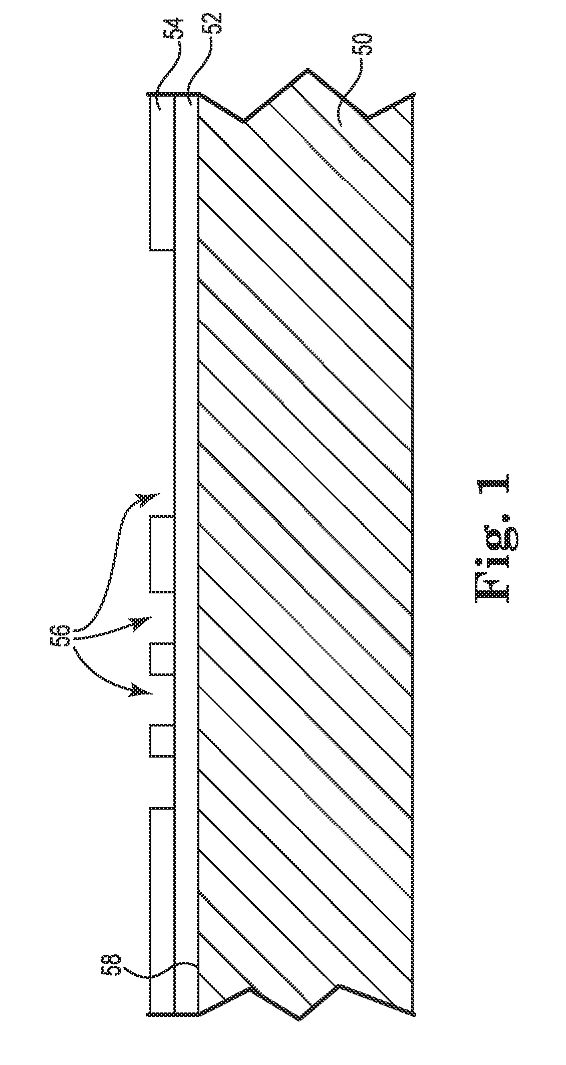
[0055]FIG. 1 is a side cross-sectional view of a method for replicating a compliant printed circuit for a semiconductor tester interface using additive processes in accordance with an embodiment of the present disclosure. Substrate 50 is a platform for the fabrication process, but may also be used in the finished tester interface.

[0056]One or more dielectric layers 52, 54 are preferably printed on surface 58 of the substrate 50 to create recesses 56 corresponding to a desired circuit geometry. Alternatively, the recesses 56 can be defined by embossing, imprinting, chemical etching with a printed mask, or a variety of other techniques. A number of different materials are used as the substrate 50 including: polyester (PET), polyimide (PI), polyethylene napthalate (PEN), Polyetherimide (PEI), along with various fluropolymers (FEP) and copolymers. Polyimide films are the most prevalent due to their advantageous electrical, mechanical, chemical, and thermal properties.

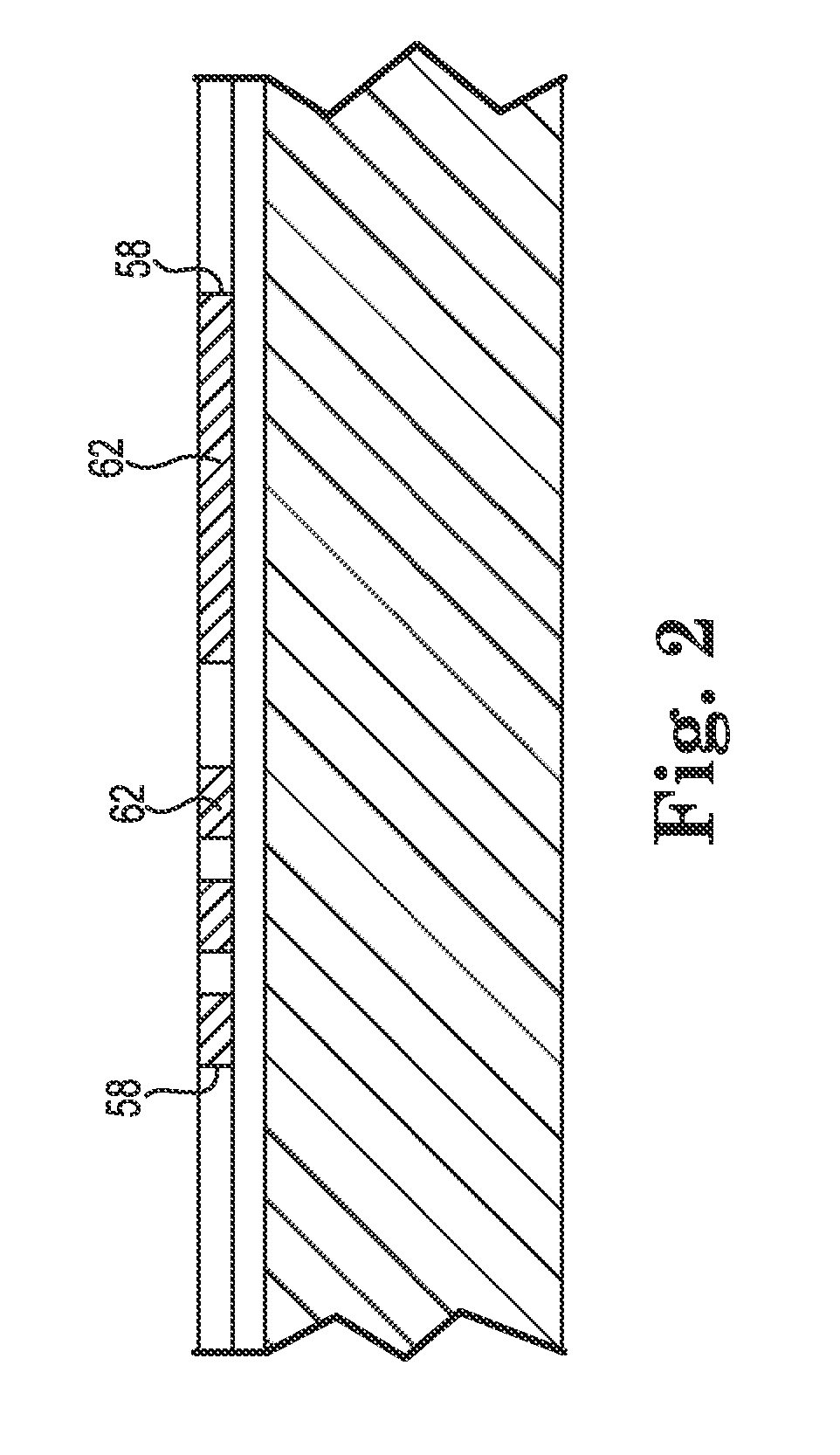
[0057]As illustrate...


PUM

PropertyMeasurementUnit
aspect ratioaaaaaaaaaa

Abstract

A compliant printed circuit semiconductor tester interface that provides a temporary interconnect between terminals on integrated circuit (IC) devices being tested. The compliant printed circuit semiconductor tester interface includes at least one dielectric layer printed with recesses corresponding to a target circuit geometry. A conductive material is deposited in at least a portion of the recesses comprising a circuit geometry and a plurality of first contact pads accessible along a first surface of the compliant printed circuit. At least one dielectric covering layer is preferably applied over the circuit geometry. A plurality of openings in the dielectric covering layer are provided to permit electrical coupling of terminals on the IC device and the first contact pads. Testing electronics that to test electrical functions of the IC device are electrically coupled to the circuit geometry.

Description

TECHNICAL FIELD[0001]The present application relates to a high performance compliant printed circuit semiconductor tester interface that merges the long-term performance advantages of flexible circuits, with the flexibility of additive printing technology.BACKGROUND OF THE INVENTION[0002]Traditional printed circuits are often constructed in what is commonly called rigid or flexible formats. The rigid versions are used in nearly every electronic system, where the printed circuit board (PCB) is essentially a laminate of materials and circuits that when built is relatively stiff or rigid and cannot be bent significantly without damage.[0003]Flexible circuits have become very popular in many applications where the ability to bend the circuit to connect one member of a system to another has some benefit. These flexible circuits are made in a very similar fashion as rigid PCB's, where layers of circuitry and dielectric materials are laminated. The main difference is the material set used ...

Claims


Application Information

Patent Timeline
Patent Type & Authority Patents(United States)
IPC IPC(8): G01R31/02G01R1/04G01R1/073
CPCG01R1/0466G01R1/07314G01R1/07378G01R1/0735H01L2224/16225Y10T29/49155
Inventor RATHBURN, JAMES
Owner HSIO TECH
Why Eureka
Try Eureka