
Laser lift off systems and methods

a technology of laser lift off and monolithic separation, applied in the field of material separation, can solve the problems of low yield, fractures at the border, and limited gan led manufacturing

Active Publication Date: 2015-03-24
IPG PHOTONICS CORP
View PDF41 Cites 21 Cited by
  • Summary
  • Abstract
  • Description
  • Claims
  • Application Information

AI Technical Summary

Benefits of technology

This approach significantly reduces cracking and improves productivity by efficiently separating GaN layers from sapphire substrates with minimal residual stress, allowing for more effective and rapid separation of epitaxial layers while maintaining sufficient energy for separation.

Problems solved by technology

In spite of the advantages from UV-laser lift-off, GaN LED manufacturing has been limited due to poor productivity caused by low process yield.
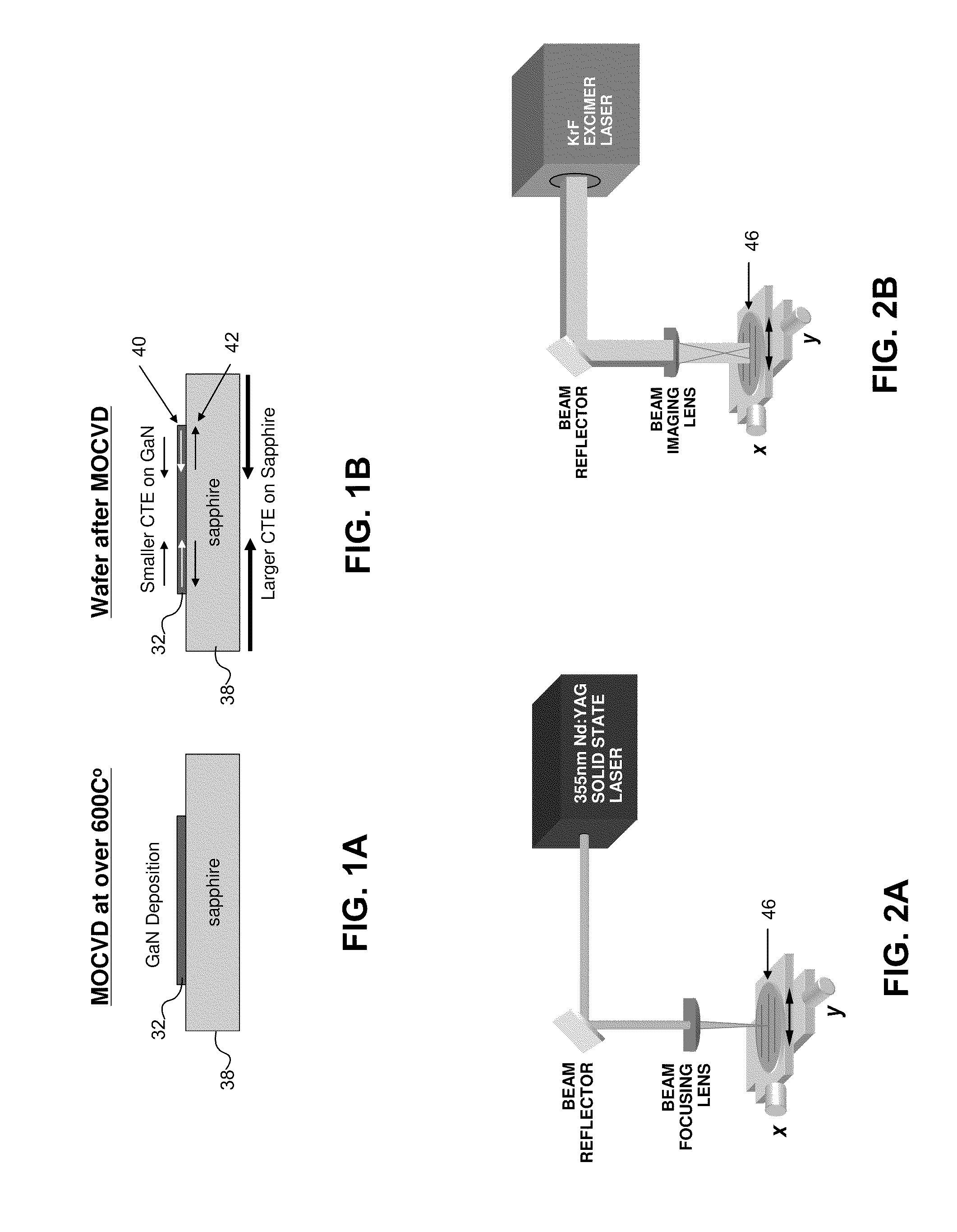
The low yield is due in part to high residual stresses in a GaN-sapphire wafer, resulting from a Metal-Organic Chemical Vapor Deposit (MOCVD) process.
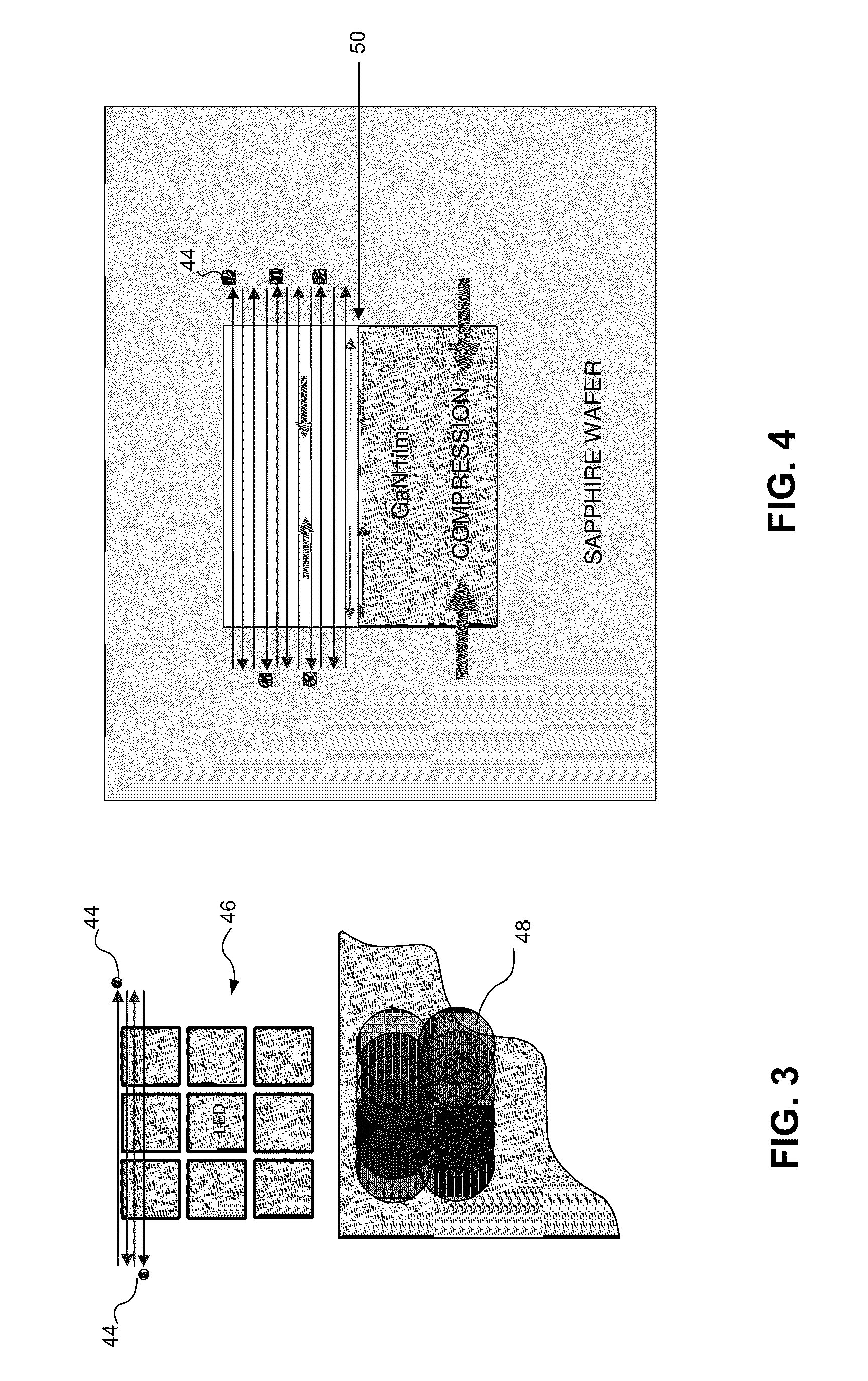
Since surroundings of the debonded area still have a high level of residual stress, it creates a concentration of stress at the bonded / debonded border, resulting in fractures at the border.
This fracturing, associated with the residual stress, has been one of the obstacles of the UV-laser lift-off process.
A problem associated with the raster scanning method is that it requires overlapping exposures to cover the desired area, resulting in multiple exposures 48 for certain locations.
The unnecessary multiple exposures in localized areas increase the potential for fracturing by inducing excessive stresses on the film.
This strain gradient may cause extensive fracturing of the GaN layer.
The explosive shock waves from the confined ablation at the GaN / sapphire interface can cause not only separation of the GaN layer from the sapphire substrate but may also fracture the GaN layer near the laser beam spot (see, e.g., P. Peyre et. al., Journal of Laser Applications, vol.
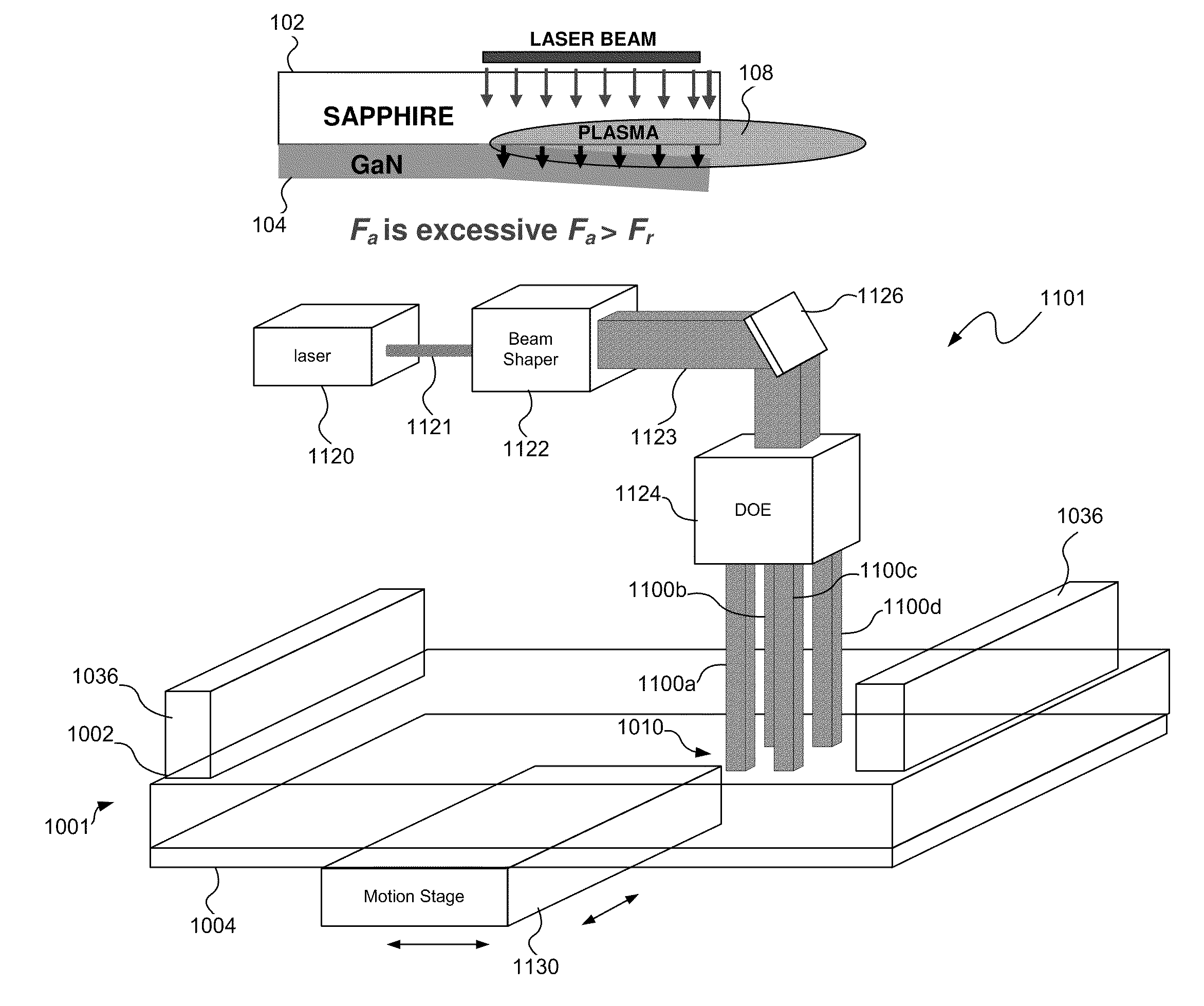
Conversely, applying overly-intense laser energy density may create excessive explosive stress wave propagation, which results in cracks and fractures on the target material 104 (e.g., the GaN film), as shown in FIG. 8C.
Although successful, the patterned lift off technique requires the additional steps of forming the streets, which results in a more time-consuming process.
Attempts at using the techniques described above to provide monolithic laser lift off, however, have been less successful because of the problems associated with residual stress.

Method used


Image

  • Laser lift off systems and methods
  • Laser lift off systems and methods
  • Laser lift off systems and methods

Examples


Embodiment Construction

[0050]Laser lift off systems and methods, consistent with the embodiments described herein, may be used to provide monolithic laser lift off with minimal cracking by reducing the size of one or more beam spots in one or more dimensions to reduce plume pressure while maintaining sufficient energy to provide separation. By irradiating irradiation zones with various shapes and in various patterns, the laser lift off systems and methods use laser energy more efficiently, reduce cracking when separating layers, and improve productivity. Some laser lift off systems and methods described herein separate layers of material by irradiating non-contiguous irradiation zones with laser lift off zones (LOZs) that extend beyond the irradiation zones. Other laser lift off systems and methods described herein separate layers of material by shaping the irradiation zones and / or by controlling the overlap of the irradiation zones in a way that avoids uneven exposure of the workpiece. Consistent with at...


PUM

PropertyMeasurementUnit
wavelengthaaaaaaaaaa
ablation depthaaaaaaaaaa

Abstract

Laser lift off systems and methods may be used to provide monolithic laser lift off with minimal cracking by reducing the size of one or more beam spots in one or more dimensions to reduce plume pressure while maintaining sufficient energy to provide separation. By irradiating irradiation zones with various shapes and in various patterns, the laser lift off systems and methods use laser energy more efficiently, reduce cracking when separating layers, and improve productivity. Some laser lift off systems and methods described herein separate layers of material by irradiating non-contiguous irradiation zones with laser lift off zones (LOZs) that extend beyond the irradiation zones. Other laser lift off systems and methods described herein separate layers of material by shaping the irradiation zones and by controlling the overlap of the irradiation zones in a way that avoids uneven exposure of the workpiece. Consistent with at least one embodiment, a laser lift off system and method may be used to provide monolithic lift off of one or more epitaxial layers on a substrate of a semiconductor wafer.

Description

CROSS-REFERENCE TO RELATED APPLICATION[0001]The present application claims the benefit of U.S. Provisional Patent Application Ser. No. 61 / 267,194 filed Dec. 7, 2009, which is incorporated herein by reference.TECHNICAL FIELD[0002]The present invention relates to separation of layers of material and more particularly, to a laser lift off systems and methods for monolithic separation of layers of material, such as a substrate and a film grown on the substrate.BACKGROUND INFORMATION[0003]Laser lift off may be used to separate layers of material. One application in which laser lift off has been used advantageously is the separation of GaN layers from sapphire substrates when manufacturing light emitting diodes (LEDs). In spite of the advantages from UV-laser lift-off, GaN LED manufacturing has been limited due to poor productivity caused by low process yield. The low yield is due in part to high residual stresses in a GaN-sapphire wafer, resulting from a Metal-Organic Chemical Vapor Depo...

Claims


Application Information

Patent Timeline
Patent Type & Authority Patents(United States)
IPC IPC(8): B32B38/10B23K26/40
CPCB23K26/4075B23K2201/40Y10S156/93B23K26/40B23K2103/50Y10T156/1917Y10T156/1158B23K2101/40Y10S156/941B32B38/0008B32B38/10B32B43/006H01L21/268H01L21/67115H01L21/7813B32B2457/14
Inventor SERCEL, JEFFREY P.MENDES, MARCOFU, JIE
Owner IPG PHOTONICS CORP
Learn More