Supercharge Your Innovation With Domain-Expert AI Agents!

Energy diffusing wear ring and methods thereof

a technology of energy diffusion and wear rings, applied in the direction of liquid fuel engines, separation processes, filtration separation, etc., can solve the problems of elastomeric liners having a short service life, premature wear of less abrasion-resistant exterior steel housings, and increased wear. it can and prevent the erosion of joints and connections

Active Publication Date: 2015-03-31
F L SMIDTH & CO AS
View PDF17 Cites 2 Cited by
  • Summary
  • Abstract
  • Description
  • Claims
  • Application Information

AI Technical Summary

Benefits of technology

The invention describes a method to reduce wear and erosion of components in a hydrocyclone or pump by diffusing high-energy slurry. This is achieved by using a special ring made of polymer or elastomer with hard inserts that create paths of resistance for the slurry to move through. This results in a reduction of wear on the components, lower energy consumption, and improved performance of the system.

Problems solved by technology

Since slurry typically contains abrasive particles which can erode interior portions of a hydrocyclone, increased wear is especially prevalent in areas with smaller inner diameters.
However, in the mid 1970's, when “componentized” cyclones were being used in coal processing, elastomeric liners had a short service life because of the abrasiveness of coal particles.
It was discovered that, unlike elastomeric liners, the gaps at each joint between the rigid ceramic liners permitted some exiting of the rotating slurry suspension within the hydrocyclone, thereby causing premature wear of less abrasion-resistant exterior steel housings.
The challenge is that ceramic liners are typically formed by slip casting or isostatic pressing while in a “green” (pre-fired) state, meaning liners need to be sized dimensionally about 15% to 17% larger than the desired final product size (post-firing), depending on material composition.
These significant shrinkage rates attributable to kiln-firing lead to non-uniformities which make it extremely difficult to close tight joint gap tolerances between ceramic liners—particularly with oddly sized or shaped liners.
Moreover, tightening of tolerances for the casting, pressing, and firing steps would lead to higher manufacturing costs and a non-competitive design in the marketplace.
However, independent tests suggest that interfitted ceramic liners incorporating such mechanical interlocks are extremely vulnerable to damage, since ceramic margins generally extend past the respective casing flange.
Moreover, such interfaces introduce a level of stress concentration.
Thus, the reliance on traditional labyrinth seals creates a vulnerable ceramic part with a poor resistance to impact.
Additionally, higher density abrasive particles have a tendency to orbit in middle and lower sections of a hydrocyclone, further increasing the chance of lap joint failure from orbiting tramp material.
The problem with these conventional sealing devices is that they fail to hold up to demanding environments, particularly environments where the sealing devices are subjected to abrasive slurries at high velocities or pressures.
Moreover, traditional mechanical interfaces which incorporate seals and gaskets fail to effectively prevent casing blowout as described above.
The aforementioned drawbacks are also prevalent in slurry pumps and upper regions of a hydrocyclone, where abrasive slurries under high pressures and / or velocities may escape between components over time.
Slurry passing through these small axial spaces may have large radial velocities and kinetic energy, and can quickly erode both the mating surfaces of the ceramic liners and adjacent portions of the surrounding casings—including flanged connections and external connectors.
Such erosion can lead to spewing, leaks, premature maintenance, and other problems with the hydrocyclone.

Method used


Image

  • Energy diffusing wear ring and methods thereof
  • Energy diffusing wear ring and methods thereof
  • Energy diffusing wear ring and methods thereof

Examples


Embodiment Construction

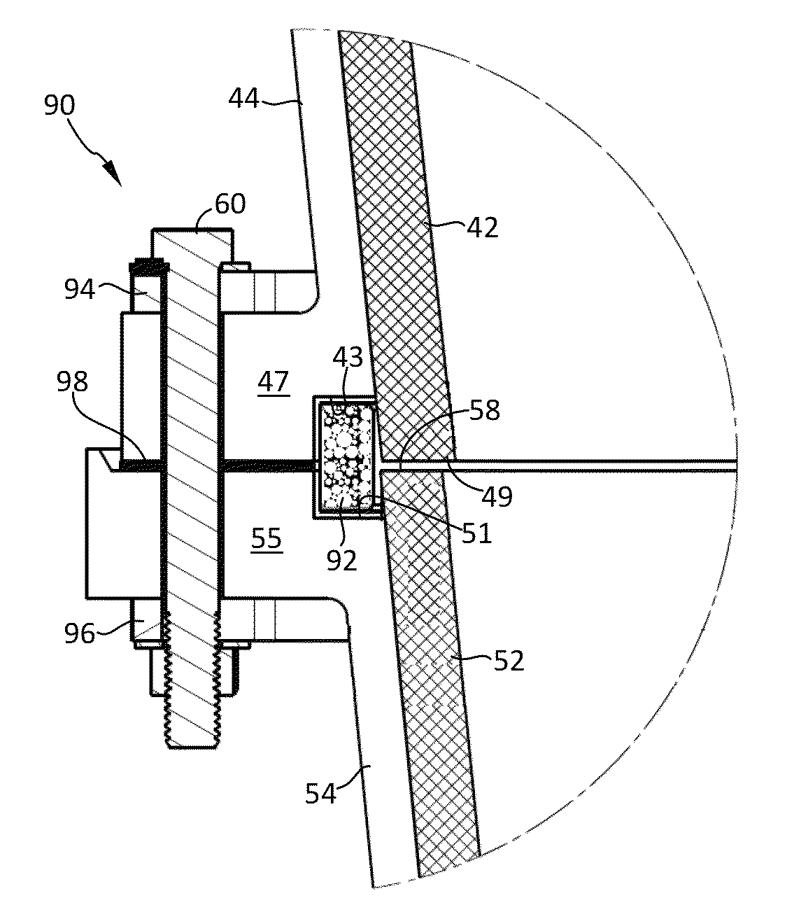
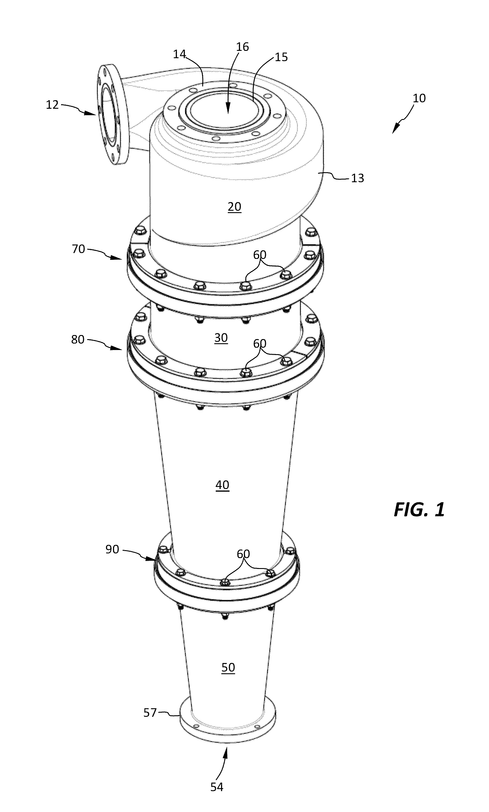
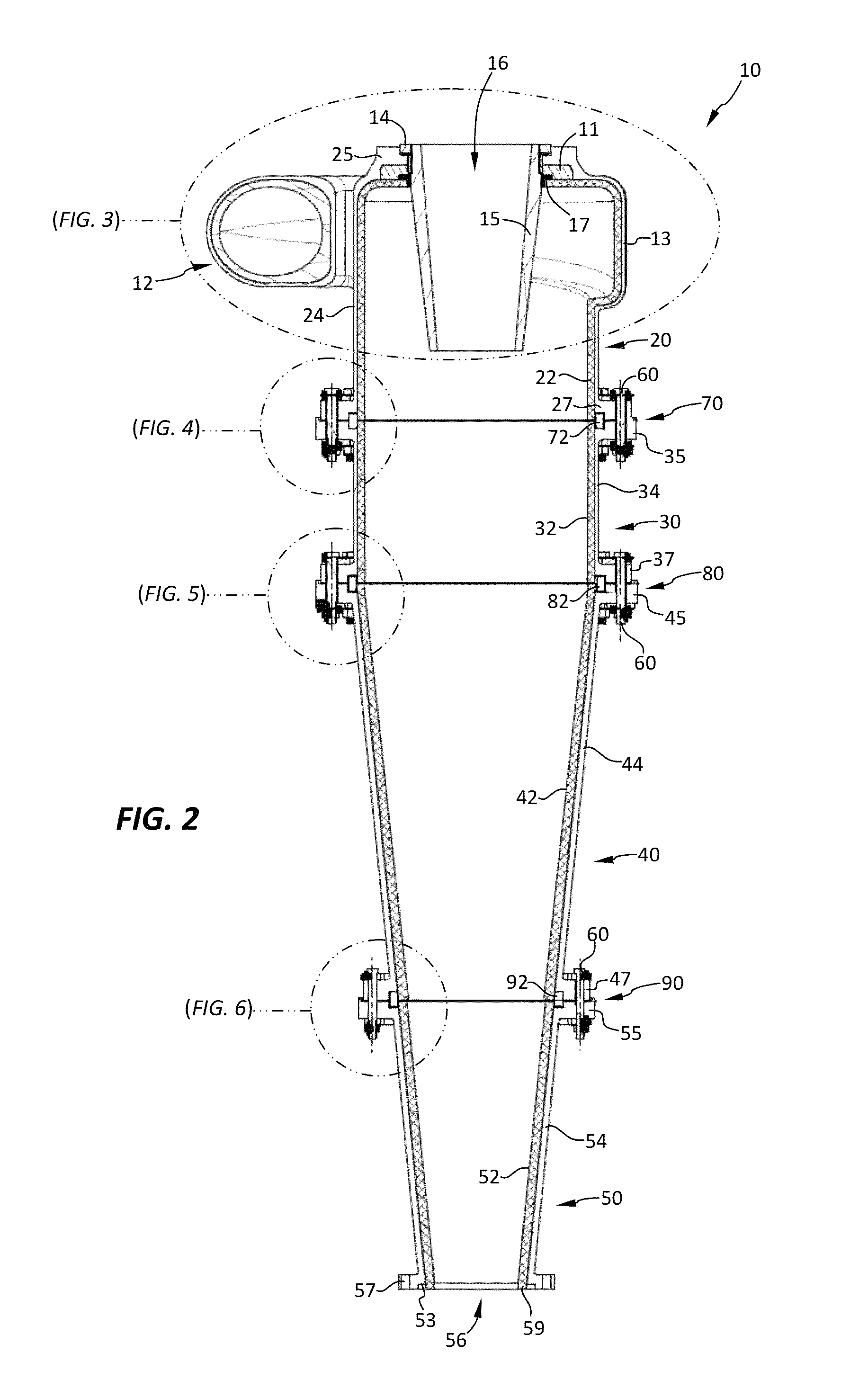
[0047]FIGS. 1-6 depict a hydrocyclone 10 according to some embodiments. The hydrocyclone 10 comprises an inlet 12 for delivery of a slurry feed to be separated. Inlet 12 is part of an inlet head 20 located at an upper region of the hydrocyclone 10. Below the inlet head 20 may be attached one or more cylinders 30 and / or cone sections 40, 50. For example, a first cone section 40 and a second cone section 50 may be provided below a single cylinder 30 as shown. The cone sections 40, 50 may taper down as they approach a lower region of the hydrocyclone 10 as shown.

[0048]In use, slurry fines entering the inlet 12 traverse a volute portion 13 and eventually exit an overflow exit port 16 defined by a vortex finder 15. Conversely, heavies and course particles in the slurry feed exit the hydrocyclone 10 through an underflow exit port 56 located in or otherwise defined by a bottommost cone section 50. The underflow exit port 56 may comprise a flange 57 or equivalent structure for connecting to...


PUM

PropertyMeasurementUnit
tangential velocityaaaaaaaaaa
diameteraaaaaaaaaa

Abstract

An energy diffusion sealing ring [872] for use with a hydrocyclone or pump is provided. The energy diffusion sealing ring [872] comprises a sacrificial suspension matrix [872A] comprised of a polymer, elastomer, or combination thereof, and a number of packed inserts [872B] suspended in the matrix [872]. The matrix [872] serves as delivery means for the inserts [872B] into one or more recessed portions [833, 841]. The inserts [872B] comprise a hard material (e.g., ceramic or carbide) and form wear bodies which slow and dissipate kinetic energy of escaping slurry by way of creating paths of resistance. As the suspension matrix [872A] erodes over time, a plurality of interstices [872C] between the inserts [872B] are formed. Escaping slurry [852] slows as it traverses three-dimensional serpentine paths defined by said interstices [872C], thereby reducing its potential to wear surrounding components. Methods for manufacturing an energy diffusion sealing ring [872] and for dissipating the energy of slurry [850] are also disclosed.

Description

CROSS-REFERENCE TO RELATED APPLICATIONS[0001]This application is a PCT international application which claims priority to U.S. provisional application No. 61 / 522,986 filed on Aug. 12, 2011.FIELD OF THE INVENTION[0002]This invention relates to consumable seals for equipment used in industrial, waste, coal, aggregate, and minerals processing technologies, and more particularly to energy-diffusing wear-resistant technologies for hydrocyclones, slurry pumps, and related apparatus.BACKGROUND OF THE INVENTION[0003]The practice of using a hydrocyclone to concentrate and separate coarser-sized particles in a particle-laden aqueous suspension has been practiced for over 100 years; however, the duty of industrial hydrocyclones has been significantly expanded over time. Today, particularly in mineral processing applications, high feed rates of solids and the abrasive nature of these particles requires that hydrocyclones be refined and improved to achieve higher capacities, greater solids recov...

Claims


Application Information

Patent Timeline
Patent Type & Authority Patents(United States)
IPC IPC(8): B04C11/00B04C5/085B04C5/08B29C45/14F16J15/16F04D29/02F04D29/40F16J15/06F16J15/10F16J15/447F16L23/18
CPCB04C11/00B04C5/085F16J15/062F16J15/102F16J15/106F16L23/18B04C5/08F16J15/447B29C45/14F04D29/026F04D29/406F16J15/16Y10T29/49826F05D2300/43F05D2300/603F05D2300/61F05D2300/20
Inventor HARWELL, TRAVISMOORHEAD, ROBERT G.
Owner F L SMIDTH & CO AS
Features
  • R&D
  • Intellectual Property
  • Life Sciences
  • Materials
  • Tech Scout
  • Unparalleled Data Quality
  • Higher Quality Content
  • 60% Fewer Hallucinations
Learn More