Ultrasensitive ratiometric capacitance dilatometer and related methods

a capacitance dilatometer and ultrasensitive technology, applied in the field of ultrasensitive ratiometric capacitance dilatometers and dilatometers, can solve the problems of large “empty cell effect, difficult to successfully implement instruments, and inability to measure thermal expansion, etc., to reduce the effect of temperature gradients, reduce the effect of adsorption gas, and improve manufacturability

Active Publication Date: 2015-03-31
QUANTUM DESIGN
View PDF10 Cites 2 Cited by
  • Summary
  • Abstract
  • Description
  • Claims
  • Application Information

AI Technical Summary

Benefits of technology

[0019]An ultrasensitive ratiometric capacitance dilatometer and related methods are described. The dilatometer provides a capacitance measurement based on a ratiometric capacitance, or the capacitance ratio measured between two or more parallel plate capacitors of the dilatometer. In this regard, an absolute capacitance bridge is not required, and even more advantageously, the effects of adsorbed gas are greatly reduced compared to conventional dilatometers. The ratiometric capacitance dilatometer provides a symmetrical configuration, which reduces the effects of temperature gradients. Moreover, certain embodiments provide a “vgroove design”, wherein a first parallel plate capacitor forms an angle with a second parallel plate capacitor of the dilatometer along a key centerline of the dilatometer cell, which improves manufacturability due to simpler grinding, metalizing and assembly. Other features and benefits will be illustrated and described in the following detailed description and the appended drawings.

Problems solved by technology

The coefficient of thermal expansion is a fundamental property of all materials; yet the capability of measuring thermal expansion is not readily available in most laboratories, especially at cryogenic temperatures on the order of few or a fraction of a degree Kelvin.
A number of dilatometers have been proposed in the art, including: furnace and push rod dilatometers used in high temperature applications; resonant frequency dilatometers used in low temperature applications; piezo-resistive dilatometers which have been shown to provide modest resolution; and capacitive dilatometers which are the most sensitive of these instruments but also the most difficult to successfully implement.
However, although well known, copper alloys have high thermal expansions, and suffer from magnetic torque on induced eddy currents which result in a large contribution to the raw expansion data from the cell itself.
This construction however suffers from the fact that insulating materials are needed to electrically isolate the capacitance plates from the body of the expansion cell which is also conducting.
In practice, these copper alloy expansion cells will typically result in a large “empty cell effect” or background signal due to the large thermal expansion of the conductive materials and or the complex copper and insulating construction of the cell itself.
Although an improvement over prior copper alloy type capacitive dilatometers, which themselves suffer from high thermal expansion, in practice, the Neumeier cell presents several problems when used within a low temperature cryostat, such as: capacity is affected by gas adsorption; an absolute capacitance measurement is required; and thermal gradients affect accuracy in 1st order.
Moreover, in all of these capacitive prior art cells, the measurement is affected by gas adsorption and thermal gradients to first order; and measurement of the absolute capacitance is required which is difficult without very specialized and expensive instrumentation.

Method used


Image

  • Ultrasensitive ratiometric capacitance dilatometer and related methods
  • Ultrasensitive ratiometric capacitance dilatometer and related methods
  • Ultrasensitive ratiometric capacitance dilatometer and related methods

Examples


examples

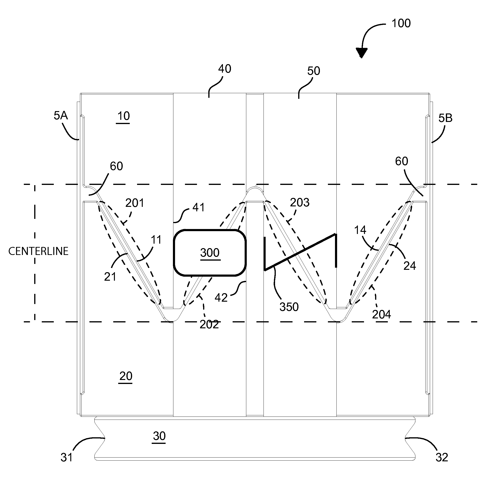
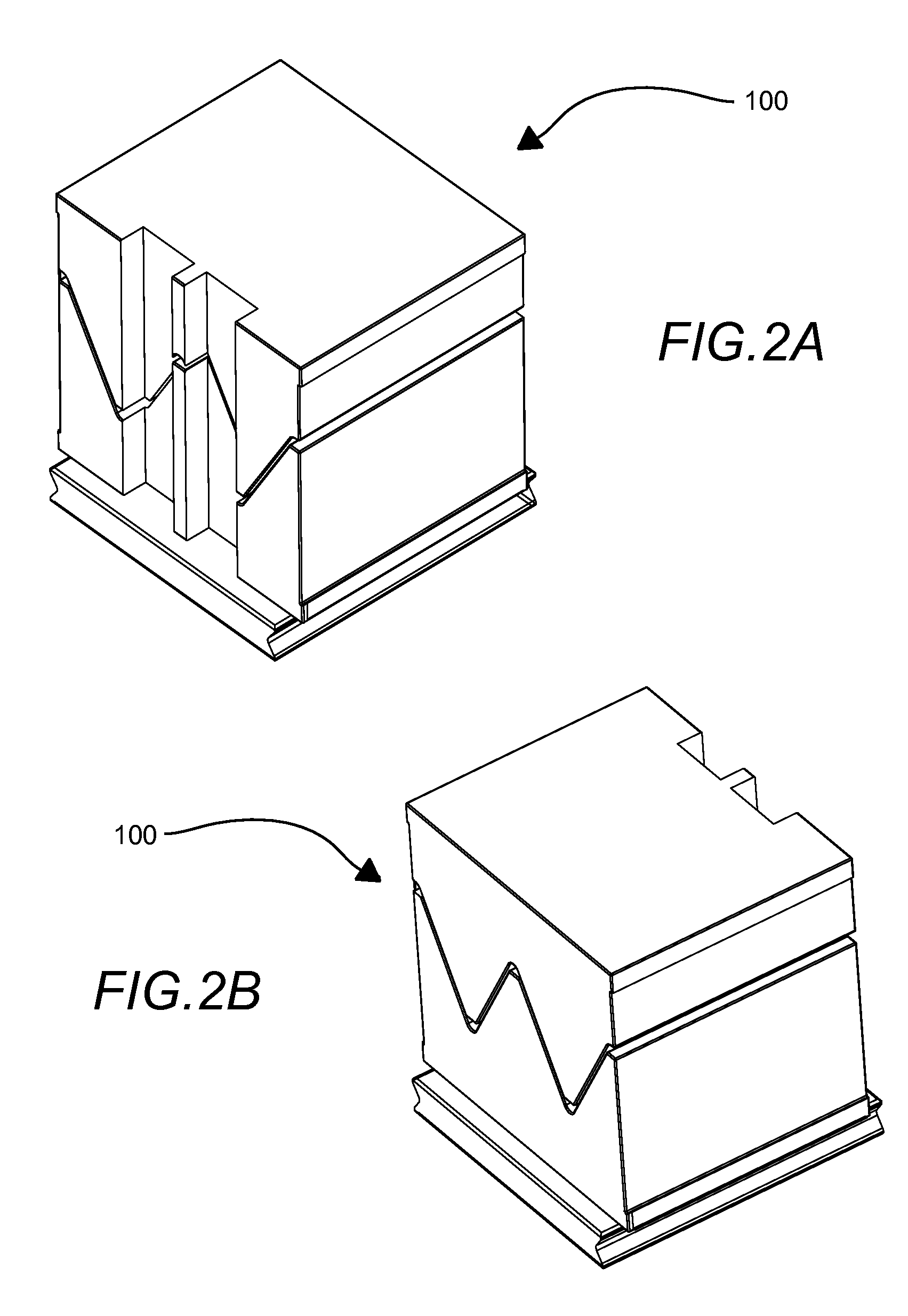
[0036]Now turning to the drawings, FIG. 2A shows a front perspective view of a ratiometric capacitance dilatometer cell 100 in accordance with one embodiment; a front side, right side, and top side of the dilatometer cell are shown.

[0037]The dilatometer cell generally comprises a cube made up of a first cell portion having one or more angled protrusions and a second cell portion having one or more angled grooves, the first cell portion being configured to nest with the second cell portion such that one or more respective surfaces of the angled protrusions are configured to oppose and overlap with respective surfaces of the angled grooves. In this regard, the first and second cell portions are nested to form a volume of the dilatometer cell, with two or more overlapping surfaces (four overlapping surfaces are shown). The cell has a right side and a left side, each of the right and left sides are configured to about one of two planar sheets referred to herein as a “springs”. A base po...


PUM

PropertyMeasurementUnit
lengthaaaaaaaaaa
temperatureaaaaaaaaaa
angleaaaaaaaaaa

Abstract

An ultrasensitive ratiometric capacitance dilatometer and related methods are described. The dilatometer provides a capacitance measurement based on a ratiometric capacitance, or the capacitance ratio measured between two or more parallel plate capacitors of the dilatometer. In this regard, an absolute capacity bridge is not required, and even more advantageously, the effects of adsorbed gas are greatly reduced compared to conventional dilatometers. The ratiometric capacitance dilatometer provides a symmetrical configuration, which reduces the effects of temperature gradients. Moreover, certain embodiments provide a “v-groove design”, wherein a first parallel plate capacitor forms an angle with a second parallel plate capacitor of the dilatometer along a key centerline of the dilatometer cell, which improves manufacturability due to simpler grinding, metalizing and assembly.

Description

CROSS-REFERENCE TO RELATED APPLICATIONS[0001]This application claims benefit of priority with U.S. Provisional Ser. No. 61 / 774,256, filed Mar. 7, 2013, and titled “DILATOMETER”; the contents of which are hereby incorporated by reference.BACKGROUND[0002]1. Field of the Invention[0003]This invention relates to high precision instruments known as dilatometers, which are designed to measure dimensional changes of a specimen brought about by changes in its environment; and more particularly, to such dilatometers configured for ratiometric measurement between two or more parallel plate capacitors, and related methods, such instruments being referred to herein as “ratiometric capacitance dilatometers”.[0004]2. Description of the Related Art[0005]The coefficient of thermal expansion is a fundamental property of all materials; yet the capability of measuring thermal expansion is not readily available in most laboratories, especially at cryogenic temperatures on the order of few or a fraction...

Claims


Application Information

Patent Timeline
Patent Type & Authority Patents(United States)
IPC IPC(8): G01N25/56G01N25/16G01N27/22
CPCG01N25/16G01N27/226G01B7/22
Inventor SIMMONDS, MICHAEL BANCROFT
Owner QUANTUM DESIGN
Why Eureka
Try Eureka