Wireless electric heat trace and vibration control and monitoring system

a technology of vibration control and monitoring system, which is applied in the direction of testing/monitoring control system, machine-to-machine/machine-type communication service, instruments, etc., can solve the problem of wide spread of problems in the entire factory

Inactive Publication Date: 2015-04-14
BRACE INTEGRATED SERVICES INC
View PDF6 Cites 22 Cited by
  • Summary
  • Abstract
  • Description
  • Claims
  • Application Information

AI Technical Summary

Benefits of technology

[0024]First, there is a central digital computer that monitors and interprets the data produced by the other control equipment. Second, there is a series of temperature / vibration sensors, one of which is located on each of the important specific pieces of equipment in the factory. Each sensor is attached to a wireless communicator (radio) designed to form a node in a MESH communication network. A MESH communicating network is a communication network in which each of the nodes is capable of receiving signals from the nodes around it and then retransmitting that signal to a node around it that moves the signal to a desired direction, in this case, toward the central computer. By adopting this MESH technology, each of the wireless communicators need only have a very short range and therefore have relatively inexpensive and have low power requirements. Thus it becomes practical to have each of the wireless communicators be battery-operated and for the battery life to be relatively long period.
[0029]The central computer uses data from these four systems to determine when each piece of factory equipment is not at the correct temperature / vibration and, by comparing the data from the four systems, diagnosis the problem on an instantaneous basis. This fast diagnosis of the problem allows the maintenance crew to address the problem quickly and usually before any permanent damage or disruption has occurred.

Problems solved by technology

Whenever those specific pieces of equipment are not operating at the proper temperature / vibration, the results can be widespread problems with the entire factory.

Method used


Image

  • Wireless electric heat trace and vibration control and monitoring system
  • Wireless electric heat trace and vibration control and monitoring system
  • Wireless electric heat trace and vibration control and monitoring system

Examples


first embodiment

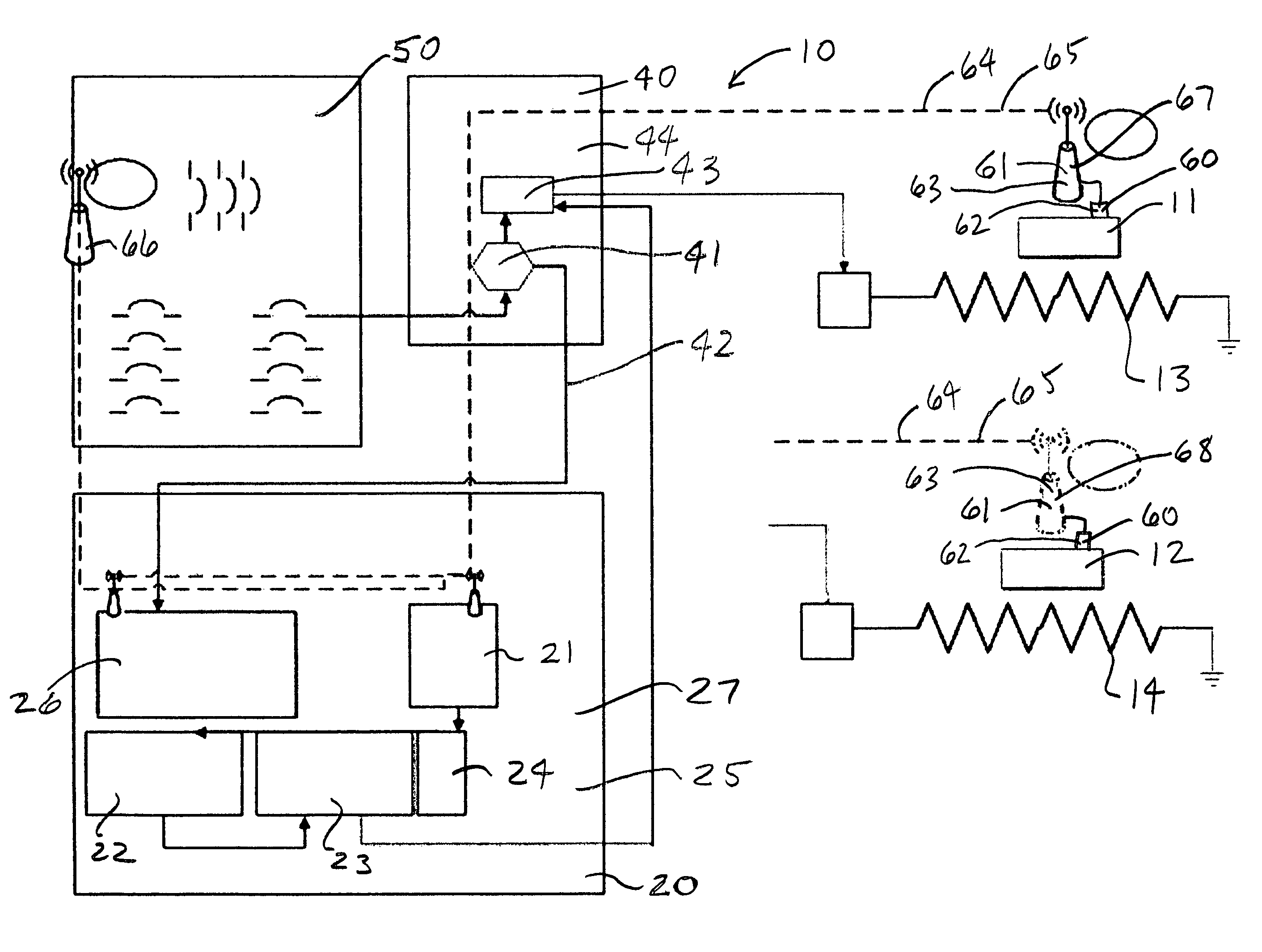
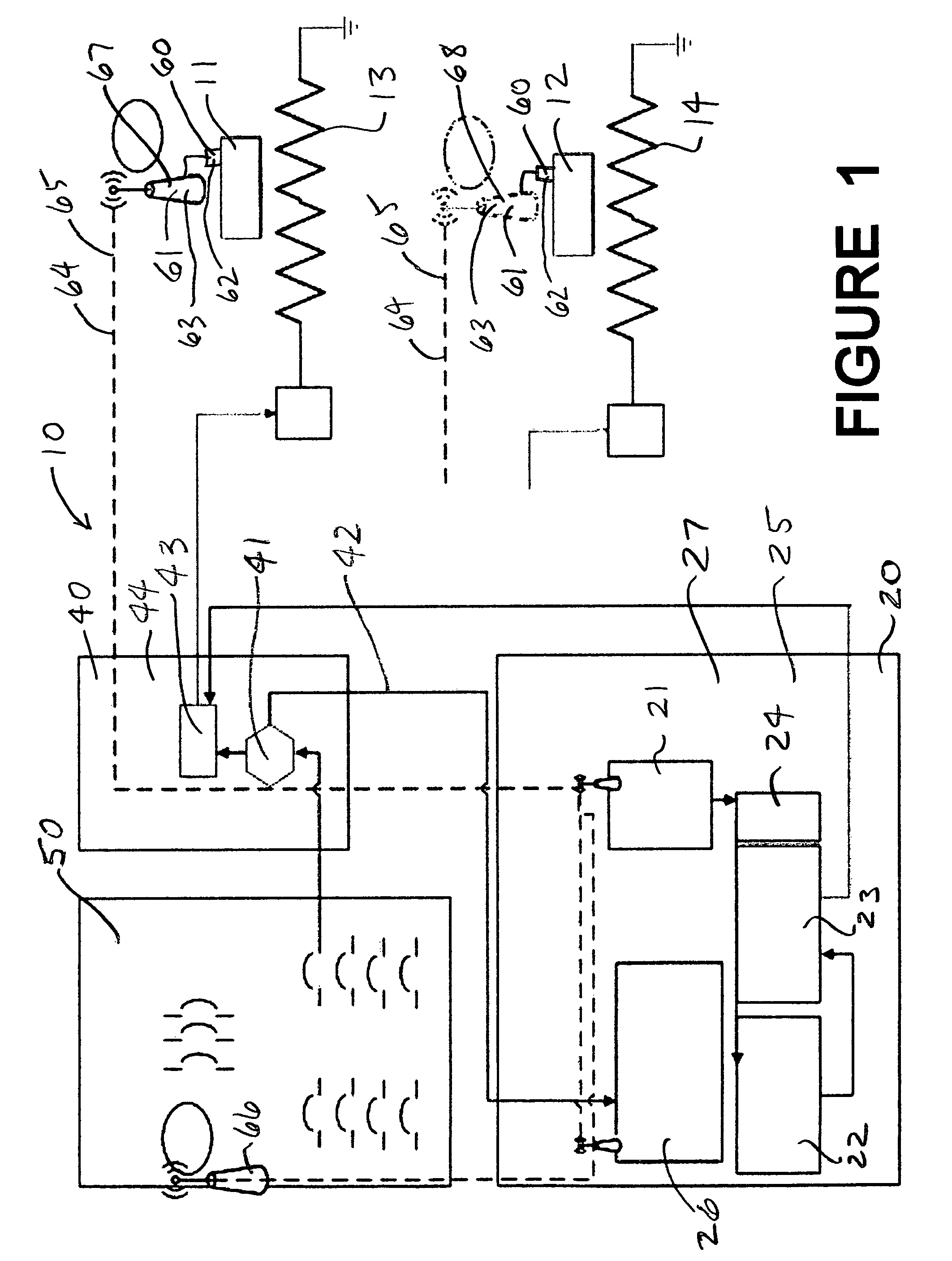
[0041]The remote sensor element 60, particularly in the first embodiment shown in FIG. 1, includes a plurality of remote temperature / vibration devices 61 (RTD's). Each of the remote temperature devices 61 includes a temperature sensor 62 that is capable of measuring an adjacent temperature, a vibration sensor capable of measuring vibration (frequency and / or amplitude) and also includes a MESH network transmitter or transceiver (radio) 63 (in the wireless case) (or a line driver in the hardwired case) capable of communicating a signal representing that temperature / vibration to the controller 22, through a communication link 64. That communication link 64 might be hardwired or might be a wireless communication link 65. One or more of the remote temperature devices (environmental temperature sensor) 66 is installed to measure environmental temperature within the facility, and other remote temperature devices / vibration (equipment temperature / vibration sensors) 67 and 68 are installed to...

third embodiment

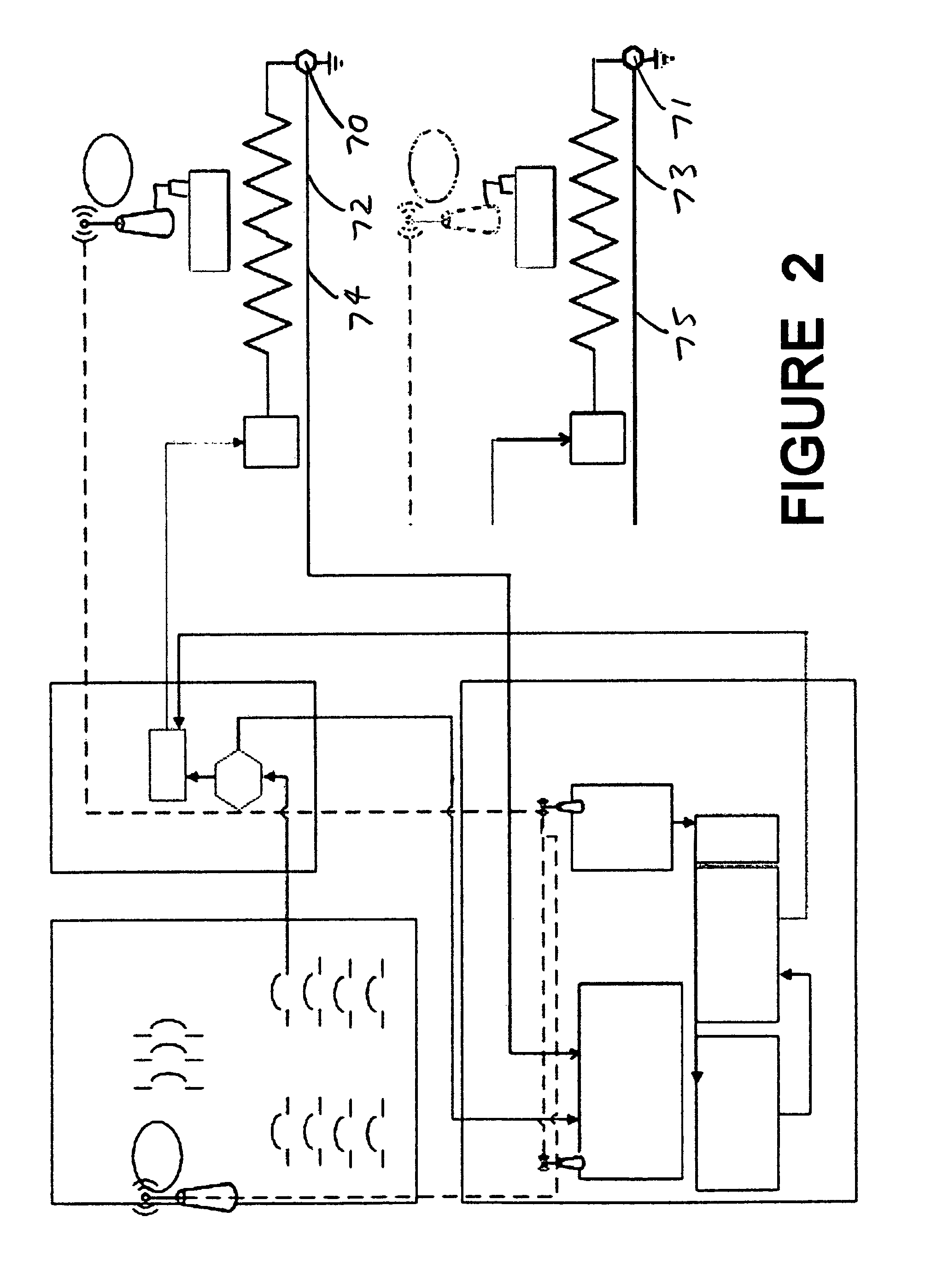
[0042]In a second and third embodiment of this invention, shown in FIGS. 2 and 3 respectively, the system includes a second current monitoring device 70 and 71 associated with each heater 11 and 12 respectively and adapted to monitor the return current from the heater and provide a signal representing that return current to the controller 22. This allows the system to compare the outgoing and returning currents in the heater circuit and thereby detect current leakage in heater circuit. The second current monitoring device 70 and 71 could be located remotely, for example, near the heater (assuming remote grounding), or could be mounted with the first circuit monitoring device 41 in the relay panel 40 (assuming a complete return line to the relay panel 40). The second current monitoring device 70 and 71 communicates its signal through a communication link 72 and 73 respectively (which could be either a hardwired communication link 74 and 75 respectively or a wireless communication lin...


PUM


Abstract

A monitoring system for monitoring the temperature and vibration of equipment, comprising a central digital computer, a MESH communication network, wherein the network feeds signals to the central digital computer, a plurality of heating elements for heating the equipment, temperature / vibration sensors adapted to measure the temperature of the equipment, wherein each sensor is adapted to provide a signal representing the temperature / vibration of the piece of equipment to which the sensor is associated, to the network, wherein each temperature / vibration sensor can also be used to control the electric heaters, a temperature sensor that monitors the ambient temperature of the facility, and current transducers associated with the heaters, to monitor the energy use and current loss of the heaters, wherein the central computer uses the data it receives from the other elements of the monitoring system to determine when the equipment is not at the correct temperature / vibration and diagnoses the reason why.

Description

CROSS-REFERENCE TO RELATED APPLICATIONS[0001]This application claims the benefit under 35 U.S.C. section 119(e) of U.S. Provisional patent application No. 60 / 976,601 filed Oct. 1, 2007, and this application is a continuation of and claims the benefit under 35 U.S.C. section 120, of U.S. patent application Ser. No. 12 / 286,732, filed Oct. 1, 2008, now pending, all of both of which are hereby incorporated by reference.STATEMENT REGARDING FEDERALLY SPONSORED RESEARCH OR DEVELOPMENT[0002]This invention has been created without the sponsorship or funding of any federally sponsored research or development program.REFERENCE TO SEQUENCE LISTING, A TABLE, OR A COMPUTER PROGRAM LISTING COMPACT DISK APPENDIX[0003]Not applicable.THE FIELD OF THE INVENTION[0004]This invention involves a system for monitoring the operation of equipment used to heat and operate industrial equipment.BACKGROUND OF THE INVENTION[0005]It is common to use an electric heat trace system in various industrial processes. In...

Claims


Application Information

Patent Timeline
Patent Type & Authority Patents(United States)
IPC IPC(8): H05B1/02G05B23/02H04Q9/00H04W4/70H04W4/80
CPCH05B1/0291G05B23/0275H05B1/023H04Q9/00H04Q2209/25H04W4/70H04W4/80H05B1/02G05D19/02G05D23/1917G05D27/02H04L67/12H04W84/22H05B1/0244G05B23/0272
Inventor MULLEN, TIMOTHY RUSSELL
Owner BRACE INTEGRATED SERVICES INC
Why Eureka
Try Eureka