Bone implant

a bone implant and bone technology, applied in the field of implants, can solve the problems of no retaining or positioning structure between the abutment and the implant, adversely affecting the function of the bite and chewing, and inconvenience for surgery, and achieve the effect of increasing structural strength and reducing manufacturing costs

Active Publication Date: 2015-04-28
METAL INDS RES & DEV CENT
View PDF8 Cites 6 Cited by
  • Summary
  • Abstract
  • Description
  • Claims
  • Application Information

AI Technical Summary

Benefits of technology

[0012]An objective of the present invention is to provide a bone implant including an easy engagement arrangement b

Problems solved by technology

Generally, biting and chewing functions will be adversely affected if a tooth defect resulting from either aging or accidental impact is not restored.
However, there is no retaining or positioning structure between the abutment and the implant before the abutment is securely fixed in the blind hole of the implant by the abutment screw.
Thus, the abutment is apt to fall out of the blind hole of the implant in a tooth implantation surgery of an upper tooth, causing inconvenience to the surgery and adversely affecting surgery efficiency.
In severe cases, the abutment falls on and stimulates the tongue of the patient, such that the patient swallows the abutment, resulting in medical disputes.
Thus, manufacturing o

Method used


Image

  • Bone implant
  • Bone implant
  • Bone implant

Examples


Embodiment Construction

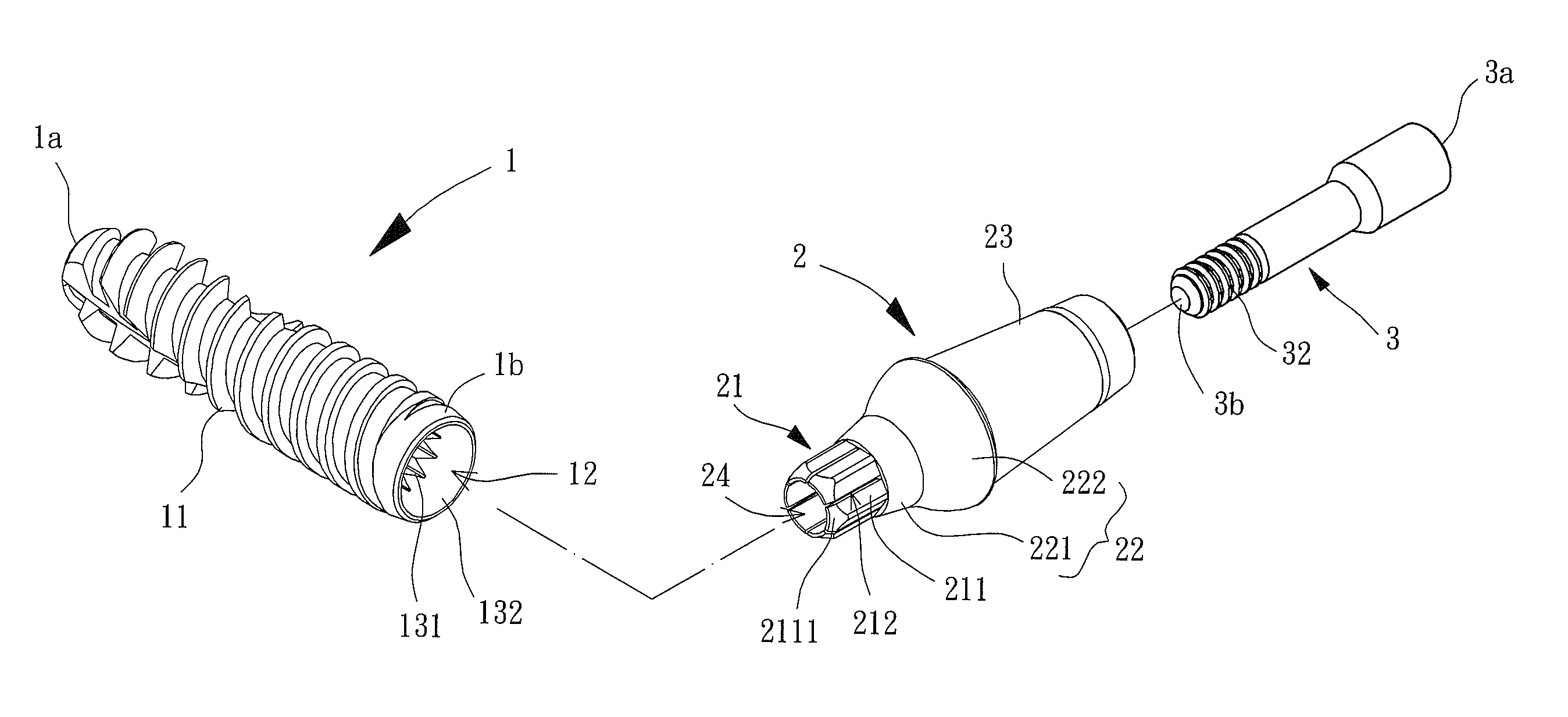
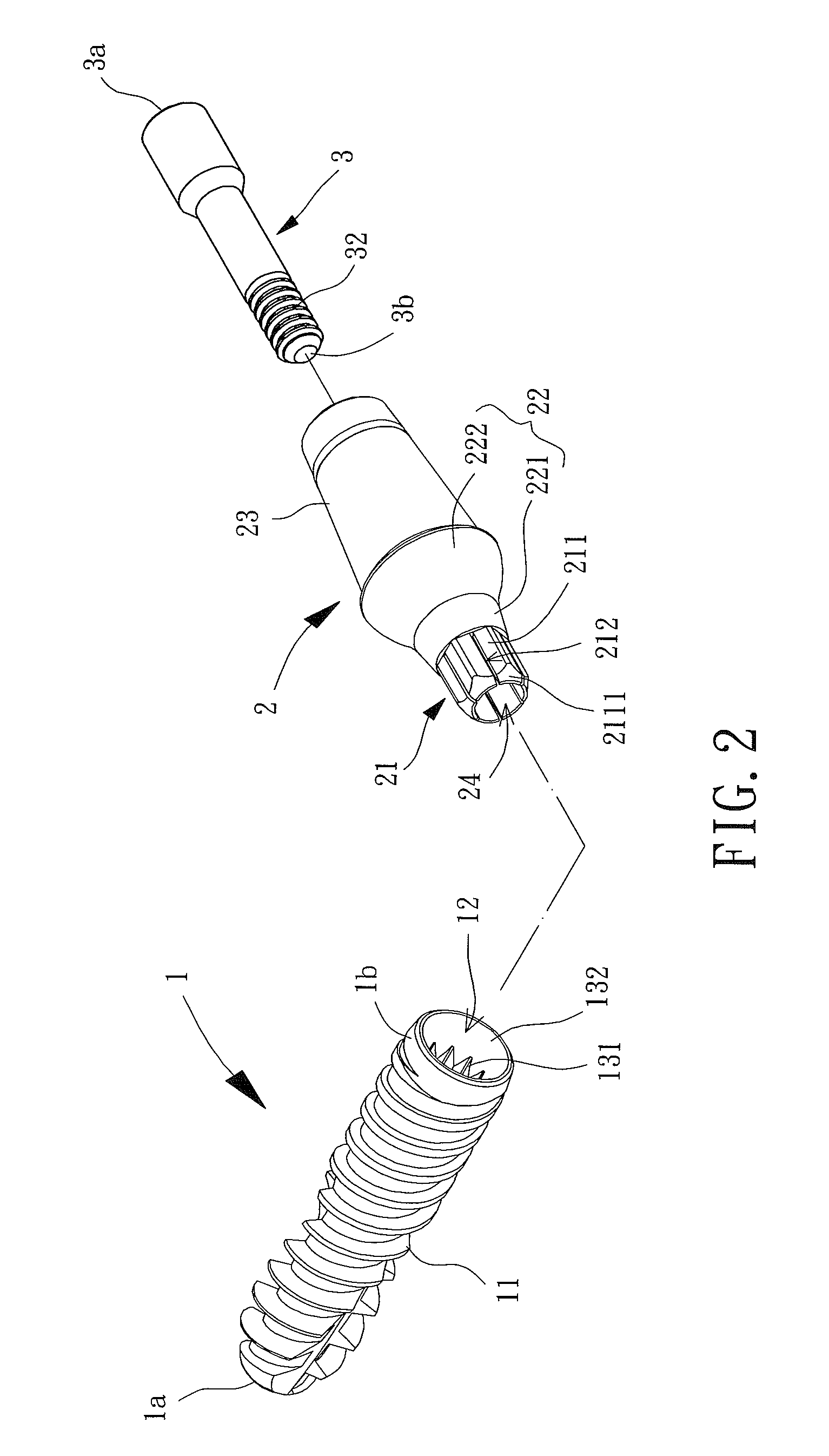
[0029]FIG. 2 shows a preferred embodiment of a dental implant according to the present invention. The dental implant according to the present invention generally includes an implant 1, an abutment 2, and an abutment screw 3. The abutment 2 is coupled to the implant 1, and the abutment screw 3 extends through the abutment 2 to securely engaging the implant 1 with the abutment 2. The implant 1 is adapted to be fixed to a bone. The abutment 2 is adapted to engage with a prosthesis such as a dental crown, artificial ear, or artificial finger. The shape and type of the implant 1 and the abutment 2 can be changed according to needs, which can be appreciated by one having ordinary skill in the art. The present invention will now be set forth with reference to an example of a bone implant for a dental crown without limiting purposes.

[0030]With reference to FIGS. 2 and 3, the implant 1 includes an implantation end 1a and a connection end 1b. The implantation end 1a is adapted to be implanted...


PUM


Abstract

A bone implant includes an implant having an implantation end and a connection end. A blind hole is formed in the connection end and extends in an axial direction, defining an abutment receiving section and a locking section. The abutment receiving section includes an anti-rotation portion having a minimal inner width perpendicular to the axial direction. An abutment includes an elastic, deformable portion, a connection portion, and a prosthesis engagement portion. The abutment further includes a bore extending in the axial direction. The elastic, deformable portion includes resilient plates, with a slit formed between two adjacent resilient plates. The elastic, deformable portion has a maximal outer width larger than the minimal inner width. The elastic, deformable portion is aligned and engages with the anti-rotation portion. An abutment screw includes a head end positioned in the bore of the abutment and a locking end engaged with the locking section.

Description

BACKGROUND OF THE INVENTION[0001]1. Field of the Invention[0002]The present invention relates to an implant and, more particularly, to a bone implant that can be implanted into a bone.[0003]2. Description of the Related Art[0004]Generally, biting and chewing functions will be adversely affected if a tooth defect resulting from either aging or accidental impact is not restored. In severe cases, after effects, including forward declination of a tooth behind the location of a missing tooth, shrinkage of bone, and a change of the face shape, occur. Among various methods for tooth restorations, tooth implantation is becoming more and more popular due to the advantages of the lack of harm to natural teeth on two sides of the location of the missing tooth, of being easy to clean, of not causing feeling of a foreign substance, and of an aesthetic appearance after implantation.[0005]Tooth implantation includes implanting a dental implant made of a medical grade material (such as titanium or ...

Claims


Application Information

Patent Timeline
IPC IPC(8): A61C8/00
CPCA61C8/0022A61C8/0057A61C8/0068A61C8/006
Inventor TSAI, TUNG-LINPAN, BO-WEICHEN, YI-CHINWANG, PEI-HUA
Owner METAL INDS RES & DEV CENT
Why Eureka
Try Eureka