
Instrument for sizing nanoparticles and a component therefor

a technology of nanoparticles and instruments, which is applied in the direction of instruments, particle separator tube details, separation processes, etc., to achieve the effect of facilitating compact and portable design, improving serviceability, and improving air flow and filtration

Active Publication Date: 2015-05-19
TSI INC
View PDF7 Cites 1 Cited by
  • Summary
  • Abstract
  • Description
  • Claims
  • Application Information

AI Technical Summary

Benefits of technology

[0007]In a related embodiment, an improved nanoparticle sizer instrument is described herein that facilitates portability and operation with other optical sizers to increase particle size measurement range. In one example embodiment, three orders of size magnitude, such as from about 10 nanometers to about 10 microns, is measurable and facilitates real-time data collection. In related embodiments, the sizing system described herein will size particles down to the 2.3 nm and 1 nm size. Sizing below these levels may necessitate alterations in some hardware components. In addition, portability is improved with the use of long life (about 8 hours), hot swappable batteries or alternatively, fuel cells. The general concepts described herein are applicable to other aerosol instruments and are not just limited to nanoparticle sizing.
[0009]In one example embodiment of the invention, a filtration manifold for use in connection with a nanoparticle sizer is described that improves serviceability, air flow and filtration as well as facilitating a compact and portable design. In addition, the overall manifold construct and modular arrangement of the manifold can be used in other aerosol instruments. In this example embodiment, the manifold design is an integrated, multi-unit system that includes pressure / flow controls, a series of coaxial pressure taps and a series of interconnected filters. The manifold assembly is also a modular system that is ideal to route airflow or stream inlets and outlets wherever convenient to effectuate the desired interconnections. In related embodiments, the manifold assembly is configured for use in most particle instruments and in most miniature devices that require serviceable filtered air handling / routing such as gas instruments, small scale nanoparticle manufacturing, and semiconductor and pharmaceutical manufacturing applications.

Problems solved by technology

Sizing below these levels may necessitate alterations in some hardware components.

Method used


Image

  • Instrument for sizing nanoparticles and a component therefor
  • Instrument for sizing nanoparticles and a component therefor
  • Instrument for sizing nanoparticles and a component therefor

Examples


Embodiment Construction

[0019]Following below are more detailed descriptions of various related concepts related to, and embodiments of, methods and apparatus for an improved system and method for sizing particles in the nanometer range for various applications. It should be appreciated that various aspects of the subject matter introduced above and discussed in greater detail below may be implemented in any of numerous ways, as the subject matter is not limited to any particular manner of implementation. Examples of specific implementations and applications are provided primarily for illustrative purposes.

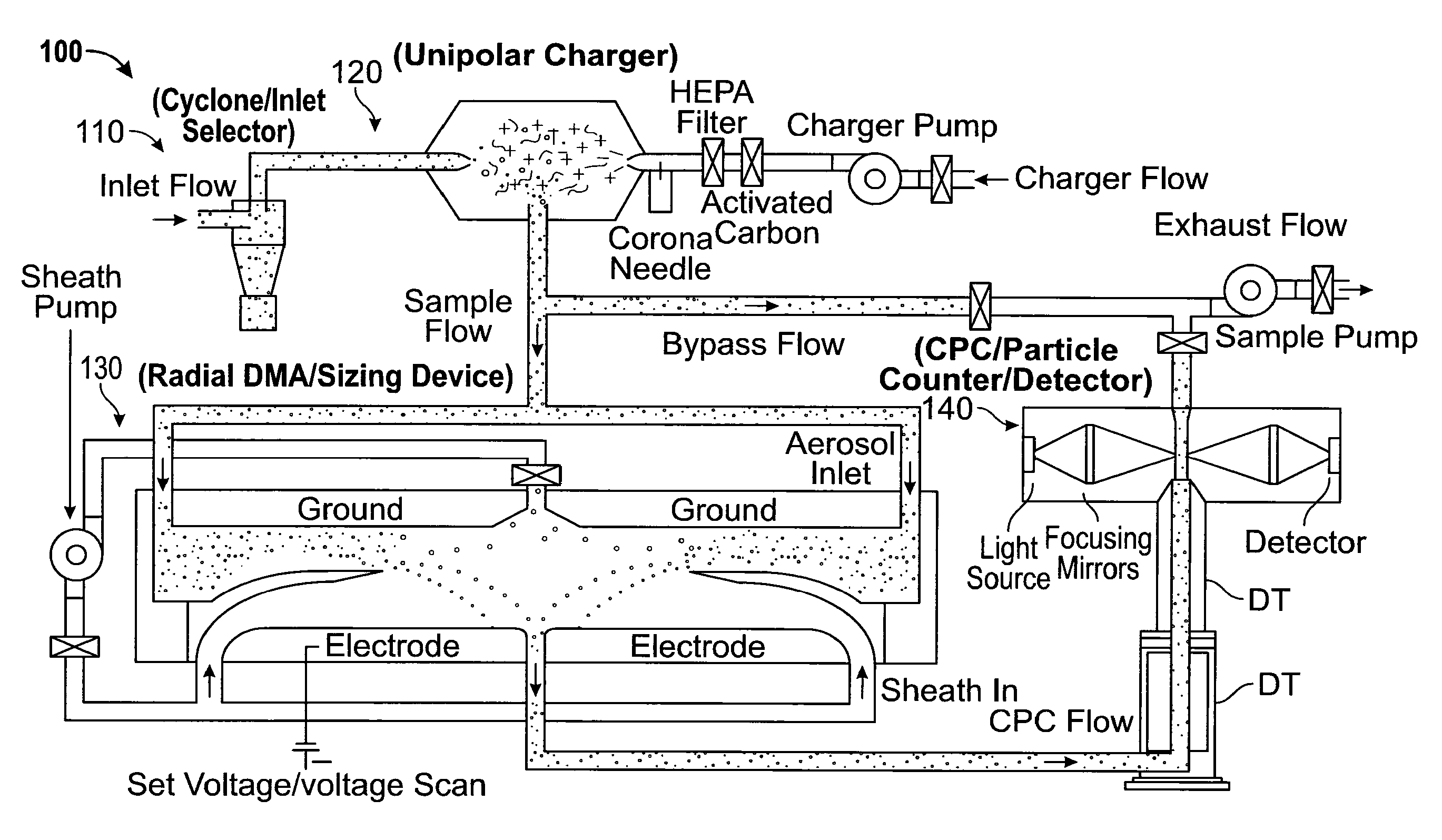
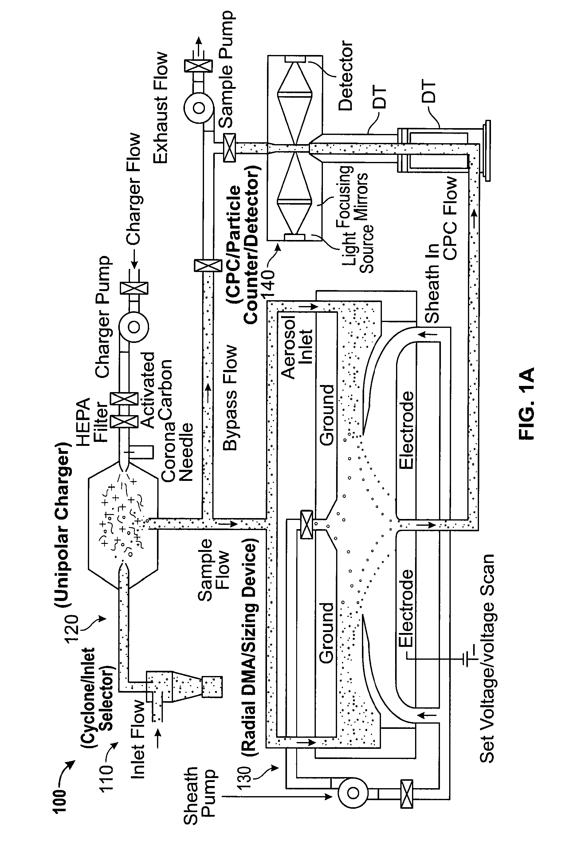
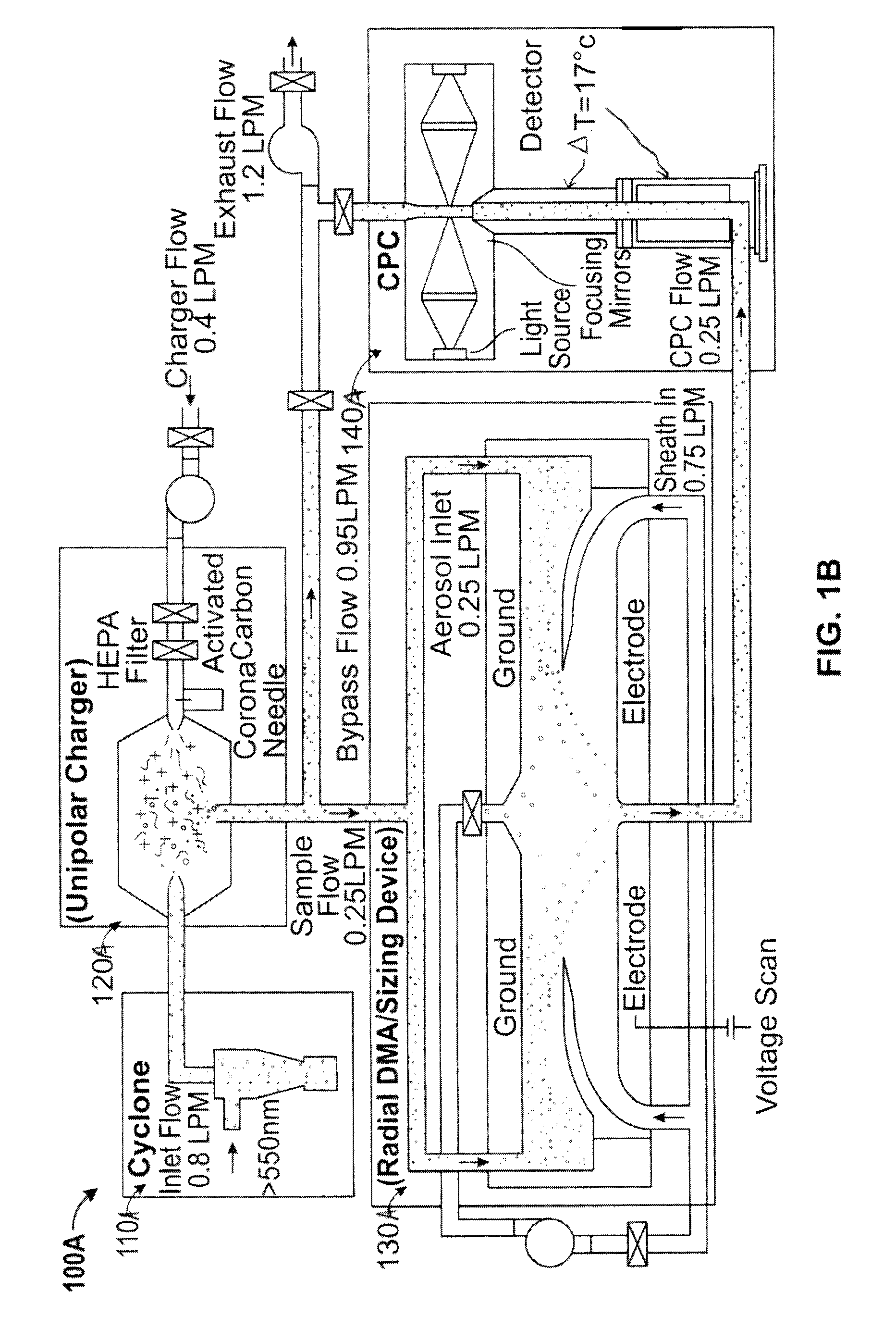
[0020]Referring now to FIGS. 1A-1B, there is shown an example embodiment of high level schematics of the nanoparticle sizing systems as well as a detailed example of a nanoparticle sizing system according to the invention. For purposes of simplicity, like numerals for like components will be used throughout the various figures disclosed herein with variations being designated as “a” or “b”. A related sys...


PUM

PropertyMeasurementUnit
diameteraaaaaaaaaa
diameteraaaaaaaaaa
size distributionsaaaaaaaaaa

Abstract

An improved nanoparticle sizing apparatus comprised of a unipolar charger operatively coupled to a radial differential mobility analyzer in combination with a condensation particle counter and powered by a power source such as a battery or solar cell, thereby providing a portable sizing device.

Description

CLAIM OF PRIORITY TO PRIOR APPLICATION[0001]The present application claims priority to International Application No. PCT / US2013 / 022224, filed on Jan. 18, 2013, which in turn claims priority to and the benefit of U.S. Provisional Application No. 61 / 589,098, filed Jan. 20, 2012, the disclosures of which are hereby incorporated by reference in their entireties.BACKGROUND OF THE INVENTION[0002]The invention relates to systems and devices for measuring concentrations of nanometer or ultrafine particles, and more particularly to such systems that are adjustable in terms of their sensitivities to certain sizes or electrical mobilities of particles or sets of particles that fall within the nanometer size range.[0003]When materials are produced or formed in the nanometer size range, i.e. from about 1 micrometer in diameter down to molecular levels, they exhibit unique properties that influence their physical, chemical and biological behavior. Nanotechnology, the field of endeavor concerned w...

Claims


Application Information

Patent Timeline
Patent Type & Authority Patents(United States)
IPC IPC(8): H01J49/24G01N1/22G01N15/00G01N15/02G01N15/06G01N15/10G01N27/62H01J49/22
CPCG01N27/624G01N15/10H01J49/22G01N15/065G01N2015/0046G01N15/0255G01N2015/0038G01N1/22G01N2015/1087
Inventor CALDOW, ROBERTJOHNSON, JASON
Owner TSI INC
Learn More