Brightness multi-emitter laser diode module and method

a laser diode module and multi-emitter technology, applied in the direction of optical elements, semiconductor lasers, instruments, etc., can solve the problems of unfavorable bpps in either axis, fiber-coupled laser diode modules still do not reach their theoretically achievable brightness, and most multi-mode fiber-coupled diodes have relatively poor brightness. achieve the effect of improving the brightness performance of multi-emitter laser diode modules

Active Publication Date: 2015-05-26
LUMENTUM OPERATIONS LLC
View PDF7 Cites 4 Cited by
  • Summary
  • Abstract
  • Description
  • Claims
  • Application Information

AI Technical Summary

Benefits of technology

[0022]The present disclosure improves the brightness performance of multi-emitter laser diode modules by modifying the optics to provide a more steeply sloped near-field intensity distribution in the fast axis at the beam spot (or fiber facet if the module is fiber-coupled). The numerical example commenced above is continued below to illustrate that when the design changes described below are implemented, in some embodiments there may be a roughly two times improvement in brightness over prior art multi-emitter laser diode module 10.
[0023]According to the present disclosure, a short focal length Fourier transform in the fast-axis can be introduced to transform the fast-axis near-field intensity distribution at the beam spot or fiber facet. The slow axis optics may remain relatively unchanged, may compensate for the additional fast-axis optics or may be transformed as well. As a result of the additional Fourier transform, the fast axis presents power intensity distributions having a steep sloped top-hat distribution in the near field and a Gaussian distribution in the far field. The steep sloped top-hat distribution in the fast-axis near field reduces the long tails that must be accommodated within the fiber core, better fills the aperture and increases brightness.

Problems solved by technology

Even with many advances over recent years, fiber-coupled laser diode modules still do not reach their theoretically achievable brightness.
Most multimode-fiber-coupled diodes have relatively poor brightness, i.e. high BPP, because broad-area diode emitters have very asymmetric BPPs in the two transverse dimensions.
Even though anamorphic optics such as prisms and cylinder lenses are able to alter spot sizes and divergences in one axis and not the other, the unfavorable BPPs do not change in either axis.
Furthermore, designs similar to the '723 patent still fall well short of the maximum theoretically achievable brightness.
If these tails were not accommodated, a considerable amount of power would be clipped at the fiber facet 31, resulting in poor power throughput as well as excessive heating and damage to the fiber.
A further drawback of the prior art occurs in applications where it is desired to provide an external feedback signal to the diode emitters.
Although desirable for reasons including cost, reliability, stability, and wavelength precision, it has to date not been practical to lock the wavelength of the emitters 12 using feedback from a wavelength-selective optic situated downstream of a fiber 30 on a multi-emitter module 10.
First, as is well-known in the art, poor brightness performance of an optical assembly causes poor power efficiency in the reverse direction.
Thus, if, for example, a wavelength-selective reflectivity of about 10% is required for reliable locking of a diode emitter, then a reflectivity of about 30% would be required in a wavelength-selective optic downstream of the fiber, resulting in an unattractively high cost of output power from the system.
Second, when light is reflected back in the fiber of prior-art fiber-coupled modules and from there transmitted into individual emitters, it has been observed that the back-reflected power is non-uniformly distributed among the emitters, with the outlying emitters receiving the least amount of feedback.
Since all of the emitters typically must be reliably locked, the required reflectivity of the downstream optic will be set by the weakest-locked emitter, and the surplus locking power provided to the other emitters will be wasted.

Method used


Image

  • Brightness multi-emitter laser diode module and method
  • Brightness multi-emitter laser diode module and method
  • Brightness multi-emitter laser diode module and method

Examples


Embodiment Construction

[0044]While preferred embodiments may be illustrated or described, they are not intended to limit the invention. Rather, numerous changes including alternatives, modifications and equivalents may be made as would be understood by the person skilled in the art. Ultimately, the invention is defined by the appended claims.

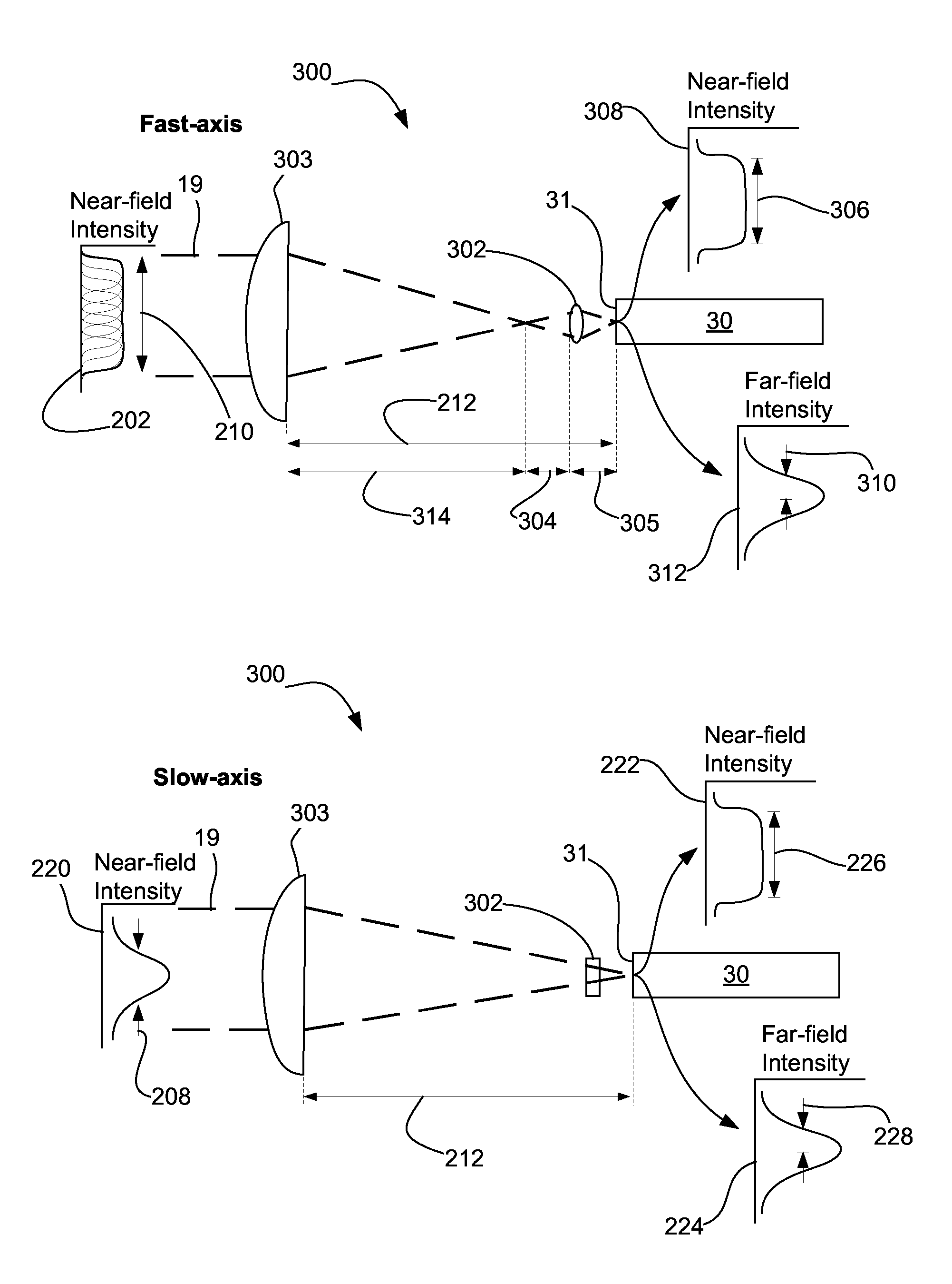
[0045]The present disclosure improves the brightness performance of existing multi-emitter diode laser modules by modifying the fast-axis optics to include a short focal length fast axis Fourier transform before the beam spot (or fiber tip if the module is fiber-coupled). This improves how sharply or steeply the near field power intensity distribution in the fast axis slopes. Increasing the slope of the fast axis near-field intensity distribution is effected by an additional transforming lens feature performing an extra Fourier transform in the fast axis, so that a steep sloped top-hat distribution is presented in the fast-axis near field. Concurrently, a more gradual...


PUM


Abstract

Improved brightness and feedback multi-emitter laser diode modules and methods are provided. A plurality of laser diode emitters emit broad-area light beams in a beam direction. In cross-section, each beam is broad in its slow axis and narrow in its fast axis. Groups of downstream optical components collimate, shape, stack and direct the beams along a light path towards a beam spot (which may be fiber-coupled). After collimating, stacking and directing, the beams are Fourier transformed in the fast-axis through a lens feature having a fast-axis focal length less than about 3 millimeters. In some embodiments, the fast-axis focal length is between about 0.1 and 2.0 millimeters. Astigmatism may be introduced between the fast axis and the slow axis in the beams upstream of the lens feature and in accordance with the fast axis focal length of the lens feature. The emitters may receive feedback including wavelength locking feedback.

Description

TECHNICAL FIELD[0001]The present invention relates to multi-emitter laser diode modules and more particularly, to improving the brightness of the beam generated by such modules at launch.BACKGROUND OF THE INVENTION[0002]Maximizing brightness of laser diode modules is important for many applications, including pumping of fiber lasers and processing of materials directly with diode radiation. Even with many advances over recent years, fiber-coupled laser diode modules still do not reach their theoretically achievable brightness. This disclosure brings the brightness significantly closer to optimum.[0003]A typical prior-art high-power multi-emitter multimode-fiber-coupled laser diode module 10 is illustrated in FIG. 1A and described, for example, in U.S. Pat. No. 7,764,723 issued Jul. 27, 2010 to Ovtchinnikov et al. (“the '723 patent”). At the most basic level, an array of diode emitters 12 output light beams 14 along a light path. In FIG. 1A, each individual diode emitter 12 in the ar...

Claims


Application Information

Patent Timeline
Patent Type & Authority Patents(United States)
IPC IPC(8): H01S5/14H01S5/10H01S5/40
CPCH01S5/4081H01S5/14H01S5/1025H01S5/405H01S5/146H01S5/4012H01S5/4062G02B6/4206G02B6/4214G02B6/43
Inventor MUENDEL, MARTIN H.
Owner LUMENTUM OPERATIONS LLC
Why Eureka
Try Eureka