Stimulated raman nanospectroscopy

a raman nano and raman spectroscopy technology, applied in the direction of spectrometry/spectrophotometry/monochromators, instruments, optical radiation measurement, etc., can solve the problems of high power lasers that can easily damage samples, weak raman effect, etc., and achieve high sensitivity and resolution. high

Active Publication Date: 2015-06-02
BRUKER NANO INC
View PDF1 Cites 26 Cited by
  • Summary
  • Abstract
  • Description
  • Claims
  • Application Information

AI Technical Summary

Benefits of technology

[0016]The current invention is directed towards providing high resolution, high sensitivity Raman spectroscopy and Raman imaging using the probe microscope (typically and AFM or similar device) with coverage over a broad portion of the mid-IR wavelengths. This is accomplished by illuminating a sample with two laser beams that overlap in sp...

Problems solved by technology

Raman spectroscopy does have some limitations, however.
First, the Raman effect is often very weak.
This has led to the use of high power lasers that can easily damage samples.
The TERS effect has shown substantial promise in some key laboratories, but has not yet to be broadly adopted due to difficulties in reliably obtaining large enhancement factors and high spatial resolution.
While conventional photoacoustic techniques...

Method used


Image

  • Stimulated raman nanospectroscopy
  • Stimulated raman nanospectroscopy
  • Stimulated raman nanospectroscopy

Examples


Embodiment Construction

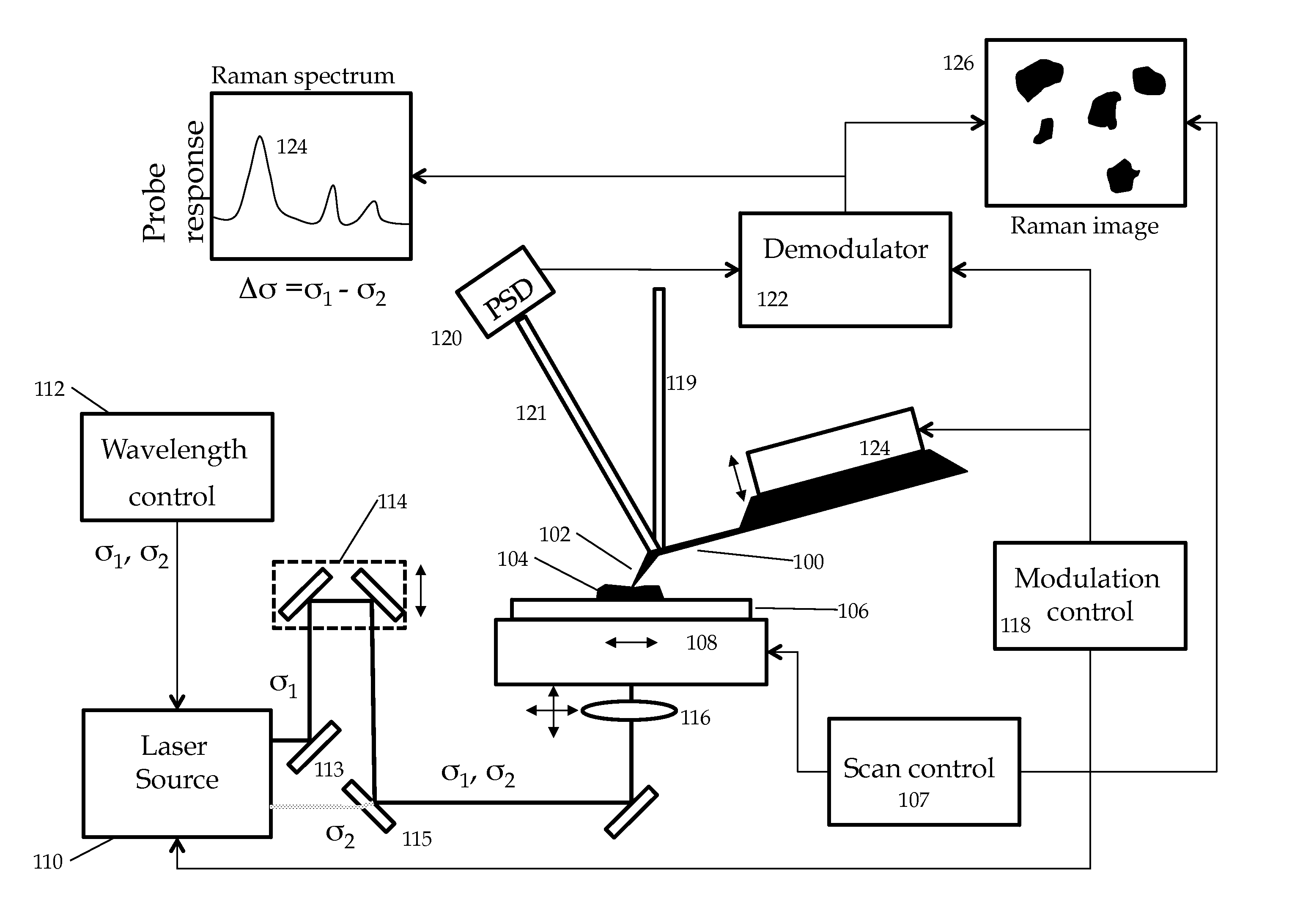
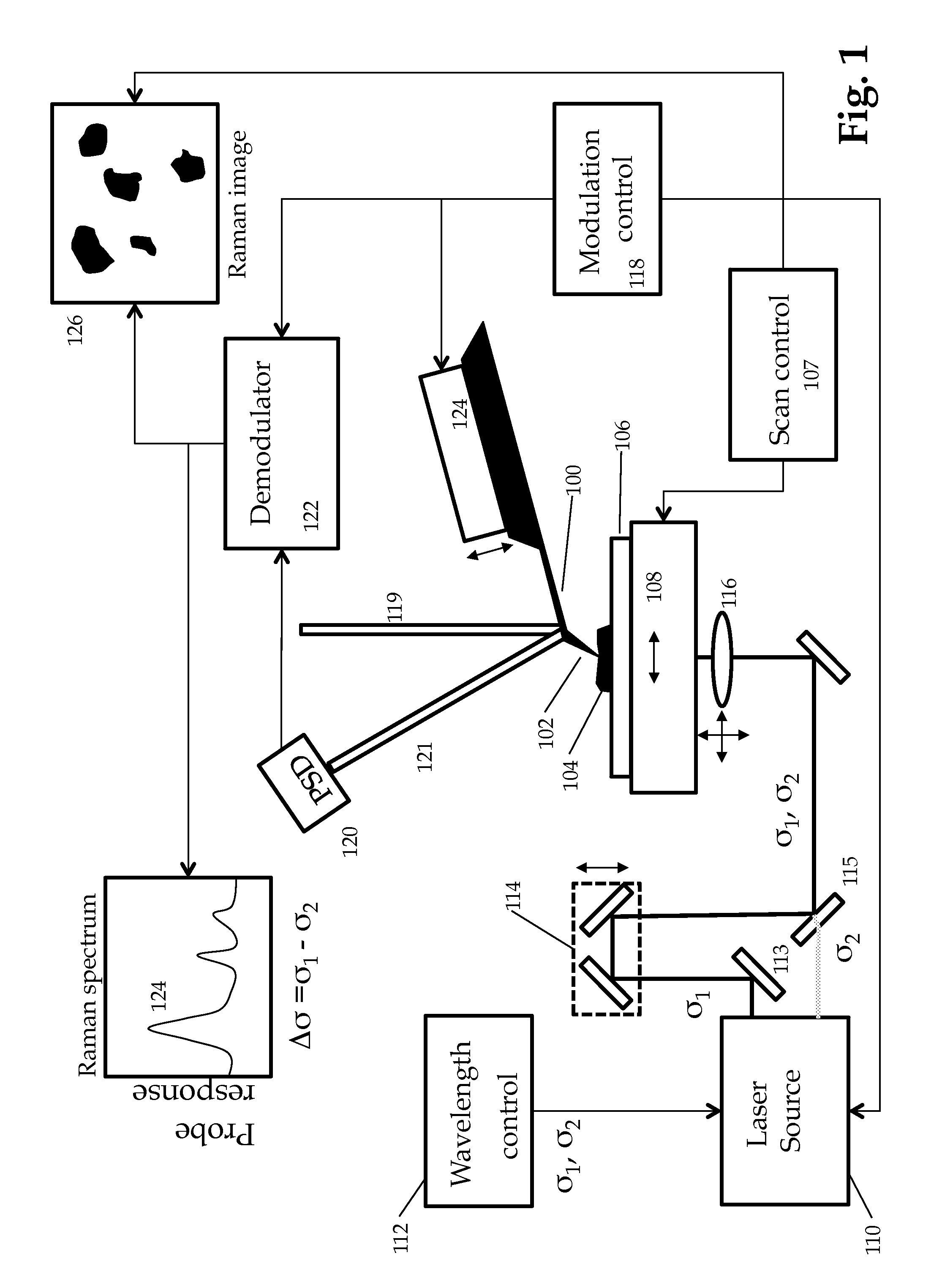
[0019]FIG. 1 shows a simplified schematic diagram of one embodiment of the current invention. An atomic force microscope cantilever probe 100 with a tip 102 is interacted with a sample 104, optionally on a support substrate 106. The tip may be interacted with the sample in contact mode, intermitted contact mode and / or non-contact mode. A probe modulator 124 can provide an oscillating signal to drive the cantilever into oscillator at one or more frequencies as supplied by modulation control 118. The modulation may include multiple modulation schemes described in copending application Multiple Modulation Heterodyne Force Microscopy U.S. Application Ser. No. 61 / 460,666 which is incorporated by reference. A laser source 110, or alternatively multiple sources, outputs at least two laser beams at frequencies σ1 and σ2.

[0020]In one embodiment the two beams at frequencies σ1 and σ2 are aligned to be substantially collinear using one or more beam steering devices shown schematically as mirro...


PUM


Abstract

A method for achieving measurable sample heating in the vicinity of a probe microscope tip using Stimulated Raman Spectroscopy. Two laser sources, preferably in the UV visible or near IR illuminate the sample, preferably in overlapping diffraction limited spots. At least one of the sources is swept through a frequency range such that the difference frequency corresponds to IR spectral regions of interest. Selective Absorption by differing sample materials at the difference frequency causes measurable sample heating detectable by the probe tip related to IR spectral absorption bands. Thus very high spatial resolution IR spectroscopy may be achieved.

Description

CROSS REFERENCE TO RELATED APPLICATION[0001]This Application claims priority to U.S. Provisional Application 61 / 556,423 filed Nov. 7, 2011STATEMENT REGARDING FEDERALLY SPONSORED RESEARCH OR DEVELOPMENT[0002]Not ApplicableBACKGROUND OF THE INVENTION[0003]The Raman effect refers to a situation where a sample is illuminated with one wavelength of light and a portion of the light is inelastically scattered, i.e. photons are emitted with a different wavelength than the incident photons. The Raman process occurs when the sample can absorb or emit a photon corresponding to the difference in energy between the incident and scattered beam. Spectroscopic measurements can be performed by measuring the amount of light scattered as a function of the difference in energy between the incident and scattered photons. This energy shift, the “Raman shift” is usually reported in wavenumbers (cm-1) that is the reciprocal of wavelength. Plotting the amplitude of scattered light versus the Raman shift all...

Claims


Application Information

Patent Timeline
IPC IPC(8): G01J3/44G01N21/01G01N21/65
CPCG01N21/658G01N21/01G01N2201/02G01Q30/02
Inventor PRATER, CRAIG
Owner BRUKER NANO INC
Why Eureka
Try Eureka