Electromagnetic-radiation power-supply mechanism for exciting a coaxial waveguide by using first and second poles and a ring-shaped reflection portion

a technology of electromagnetic radiation and power supply mechanism, which is applied in the direction of waveguide type devices, plasma techniques, coatings, etc., can solve the problem of not being able to effectively supply power, and achieve the effect of effectively supplying electromagnetic wave power

Active Publication Date: 2015-06-30
TOKYO ELECTRON LTD
View PDF14 Cites 184 Cited by
  • Summary
  • Abstract
  • Description
  • Claims
  • Application Information

AI Technical Summary

Benefits of technology

[0009]In view of the above, the present invention provides an electromagnetic-radiation power-supply mechanism and a microwave introduction mechanism using same, capable of effectively supplying an electromagnetic wave power to a coaxial waveguide even when it is not able to supply the electromagnetic wave power from an extension of the coaxial waveguide.
[0011]In accordance with the first aspect, the electromagnetic-radiation power-supply mechanism may further includes a reflecting plate provided at a side of the waveguide opposite to a power supply direction thereof, wherein the electromagnetic wave power supplied from the power supply antenna is reflected by the reflecting plate and propagates in the waveguide. Further, the electromagnetic-radiation power-supply mechanism may further include a wave retardation member, provided between the reflecting plate and the power supply antenna, for shortening an effective wavelength of an electromagnetic wave.

Problems solved by technology

In that case, it is not possible to effectively supply the power.

Method used


Image

  • Electromagnetic-radiation power-supply mechanism for exciting a coaxial waveguide by using first and second poles and a ring-shaped reflection portion
  • Electromagnetic-radiation power-supply mechanism for exciting a coaxial waveguide by using first and second poles and a ring-shaped reflection portion
  • Electromagnetic-radiation power-supply mechanism for exciting a coaxial waveguide by using first and second poles and a ring-shaped reflection portion

Examples


Embodiment Construction

[0038]Hereinafter, embodiments of the present invention will be described in detail with reference to the accompanying drawings which form a part hereof, where like features in the different drawing figures are designated by the same reference labels or descriptions.

[0039](Configuration of Surface Wave Plasma Processing Apparatus)

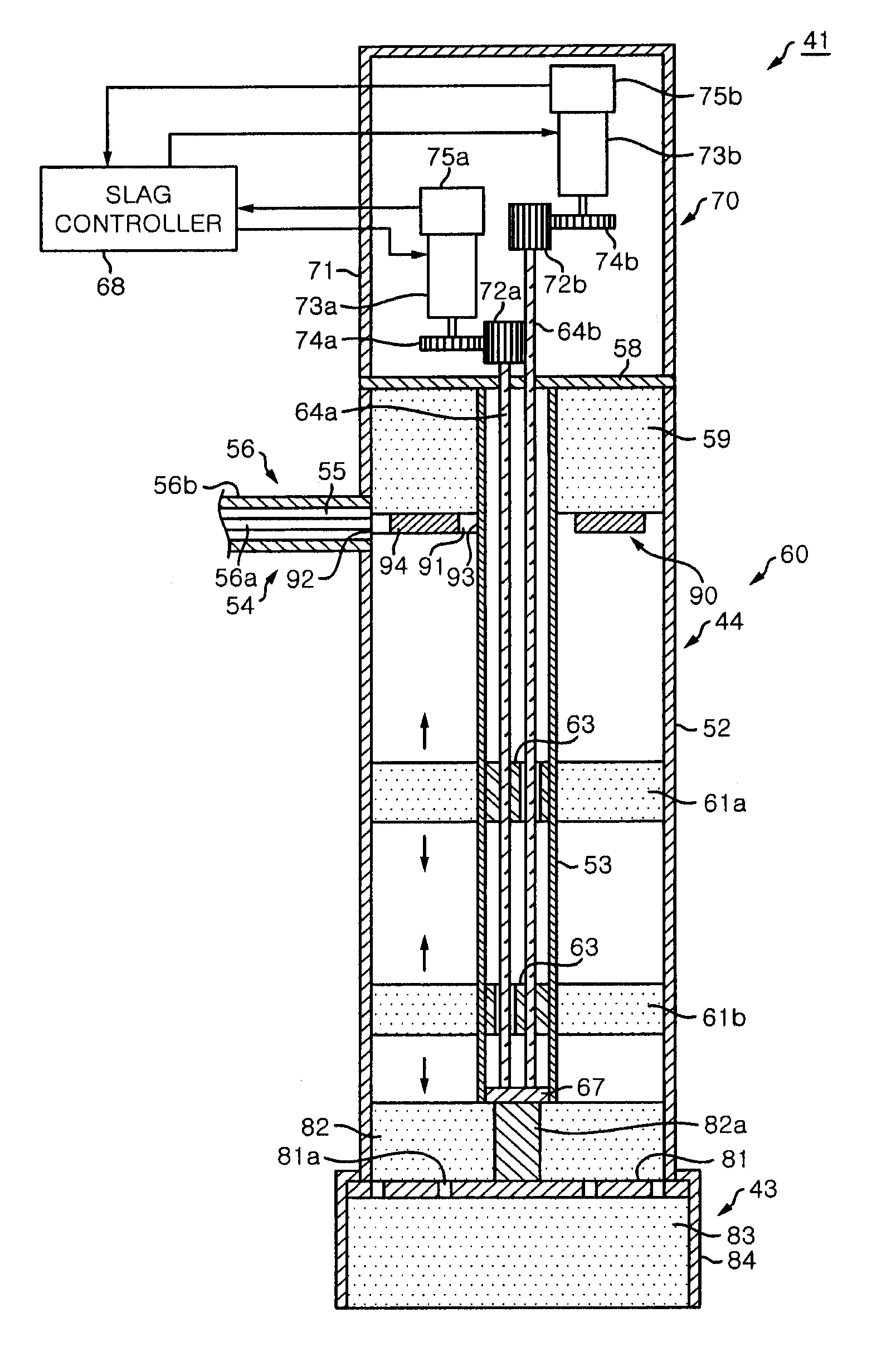
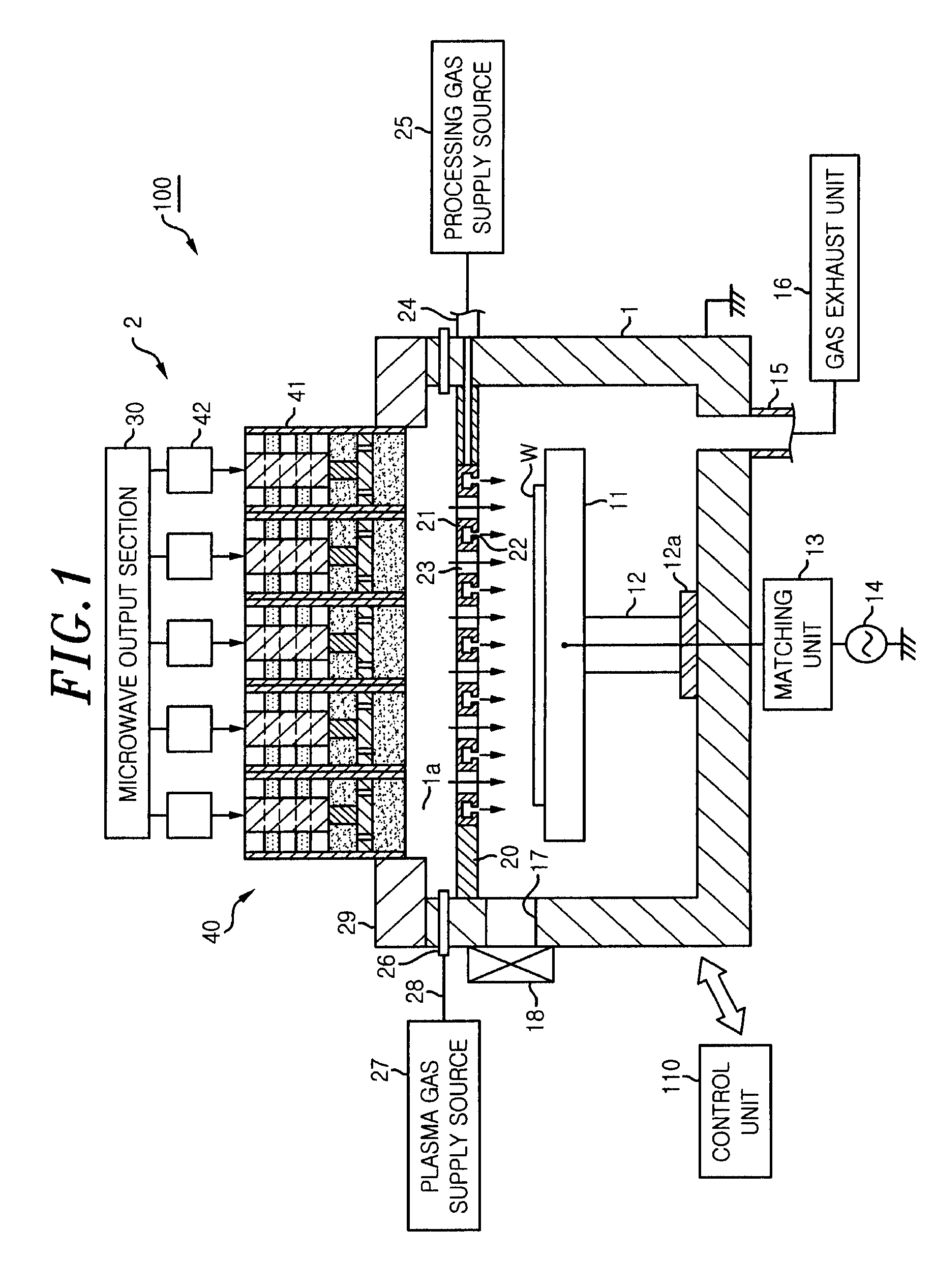
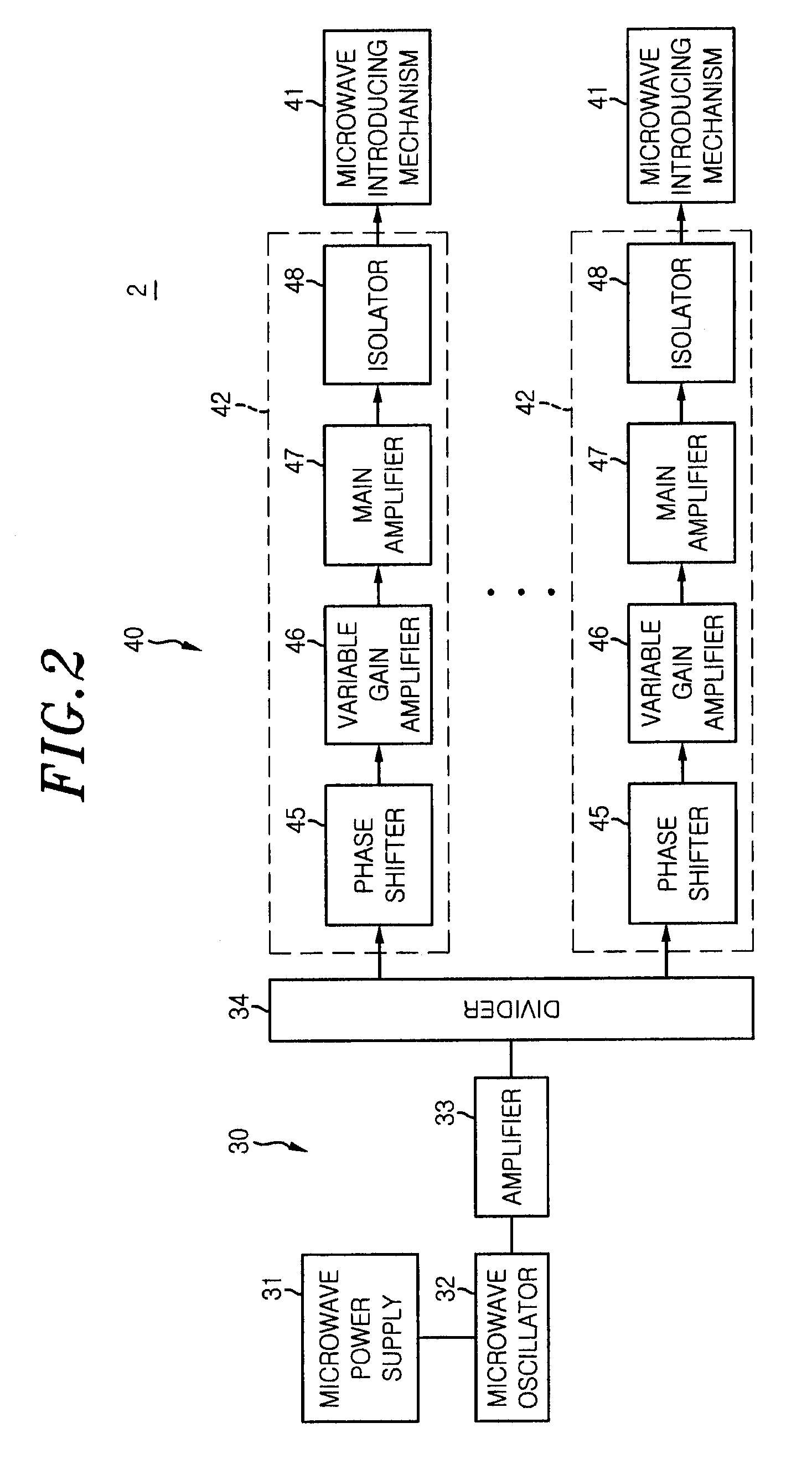
[0040]FIG. 1 is a cross sectional view showing a schematic configuration of a surface wave plasma processing apparatus including a microwave introduction mechanism to which an electromagnetic-radiation power-supply mechanism is applied in accordance with an embodiment of the present invention. FIG. 2 shows a configuration of a microwave plasma source having the microwave introduction mechanism shown in FIG. 1.

[0041]As shown in FIG. 1, a surface wave plasma processing apparatus 100 is configured as, e.g., a plasma etching apparatus for performing on a wafer an etching process as a plasma process, and includes a substantially cylindrical airtight chamber 1 ma...


PUM

PropertyMeasurementUnit
frequencyaaaaaaaaaa
frequencyaaaaaaaaaa
frequencyaaaaaaaaaa

Abstract

An electromagnetic-radiation power-supply mechanism includes a microwave power introduction port provided on the side of the coaxial waveguide, a power line being connected to the microwave power introduction port; and a power supply antenna for radiating the electromagnetic wave power into the waveguide, the power supply antenna being connected to the power line. The power supply antenna includes an antenna body having a first pole connected to the power line and a second pole connected to an inner conductor of the waveguide; and a ring-shaped reflection portion extending from opposite sides of the antenna body.

Description

[0001]This application is a Continuation Application of PCT International Application No. PCT / JP2011 / 050562 filed on Jan. 14, 2011, which designated the United States.FIELD OF THE INVENTION[0002]The present invention relates to an electromagnetic-radiation power-supply mechanism and a microwave introduction mechanism.BACKGROUND OF THE INVENTION[0003]In a manufacturing process of a semiconductor device or a liquid crystal display, a plasma processing apparatus such as a plasma etching apparatus, a plasma CVD film forming apparatus or the like is used to perform a plasma process such as an etching process, a film forming process or the like on a target substrate to be processed such as a semiconductor wafer, a glass substrate or the like.[0004]Recently, as for the plasma processing apparatus, some attention has been paid to a RLSA (Radial Line Slot Antenna) microwave plasma processing apparatus capable of uniformly generating a surface wave plasma in a high density and at a low electr...

Claims


Application Information

Patent Timeline
Patent Type & Authority Patents(United States)
IPC IPC(8): H01J37/32H05H1/46H01Q15/00
CPCH05H1/46H01J37/32192H01J37/32211H01J37/3222H01J37/32229H01Q15/0006H01J37/32293H01J37/32311H05H2001/4622H05H1/4622C23C16/511H01L21/3065H01P5/08H05H1/463
Inventor IKEDA, TAROOSADA, YUKIKASAI, SHIGERU
Owner TOKYO ELECTRON LTD
Why Eureka
Try Eureka