
Electrical propulsion and recharging technology for heavy duty vehicles

a technology of electric propulsion and recharging technology, which is applied in the direction of electric propulsion mounting, electric devices, propulsion by batteries/cells, etc., can solve the problems of limited amorphous silicon output, high cost or weight or maintenance needed to alter fossil fuel emissions, and high emission and noise pollution, so as to increase driving range and maintain cruising speed, the effect of reducing emissions

Active Publication Date: 2015-07-21
MCPARLAND DAVID BRIAN +1
View PDF8 Cites 1 Cited by
  • Summary
  • Abstract
  • Description
  • Claims
  • Application Information

AI Technical Summary

Benefits of technology

The present invention introduces a green electric heavy duty system that can fit in the existing frame under the floor of the bus or truck by removing the diesel or gas engine. The system has a limited driving range and can assist in reshaping green transportation. Driving range is increase using dual generators and dual power source that saves plug in charging time. The front driver receives rotational energy from either electromagnetic clutch or electric motor. Each generator and the electric motors are managed and engaged to cycle on or off by a computer processor unit and programmable logic controller directing power respond for maximum charge and simple quiet green electric motor rotational energy. The high horse power electric motor is engaged for heavy rotational energy demand or the low horse power electric motor is engaged to maintain cruising speed. The front output shaft of both electric motors is perpendicular lined to the driver and the rear drive and rear wheels. The system allows for individual cycling of each generator and maximizes electricity consumption or charging time or electric motor operation.

Problems solved by technology

Internal combustion powered vehicles cost or weight or maintenance needed to alter fossil fuel emissions is high the health of our children exposure to chemical cocktail emissions or green house gas emission and noise pollution are global.
Amorphous silicon output is limited to panel size and difficult to fit system on a moving vehicle also demands the sunlight to create energy night driving would be limited.
Heavy duty application could require AC or large DC motor for each wheel considerable power source is required.
If generator combination motors are used the still or slow axle rotation may not generate enough current to recharge or current to drive the other axle motor or motors.

Method used


Image

  • Electrical propulsion and recharging technology for heavy duty vehicles
  • Electrical propulsion and recharging technology for heavy duty vehicles
  • Electrical propulsion and recharging technology for heavy duty vehicles

Examples


Embodiment Construction

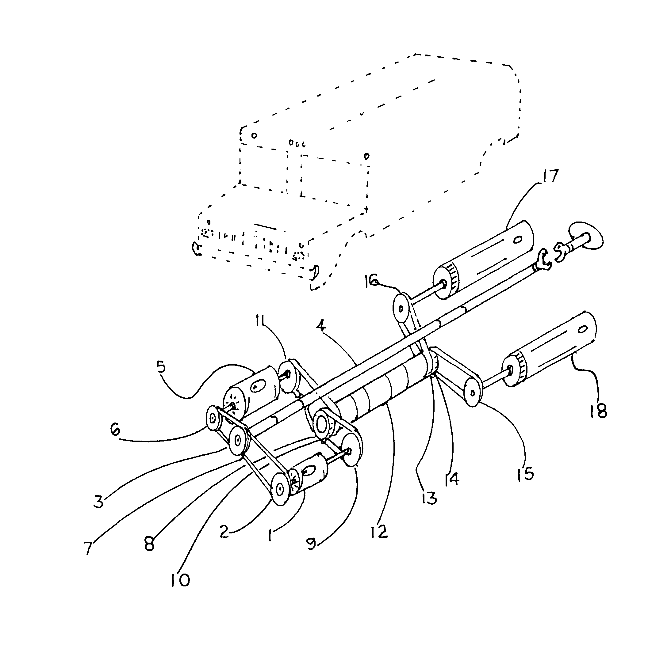
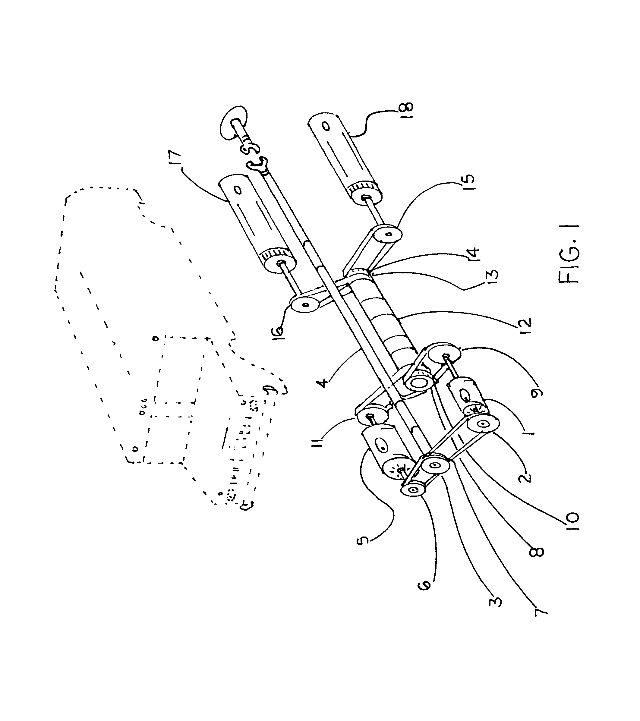
[0062]The electric traction motors (1, 5) and generators (17, 18) and connector (4) are mounted horizontally on the top of steel mount plate (35).

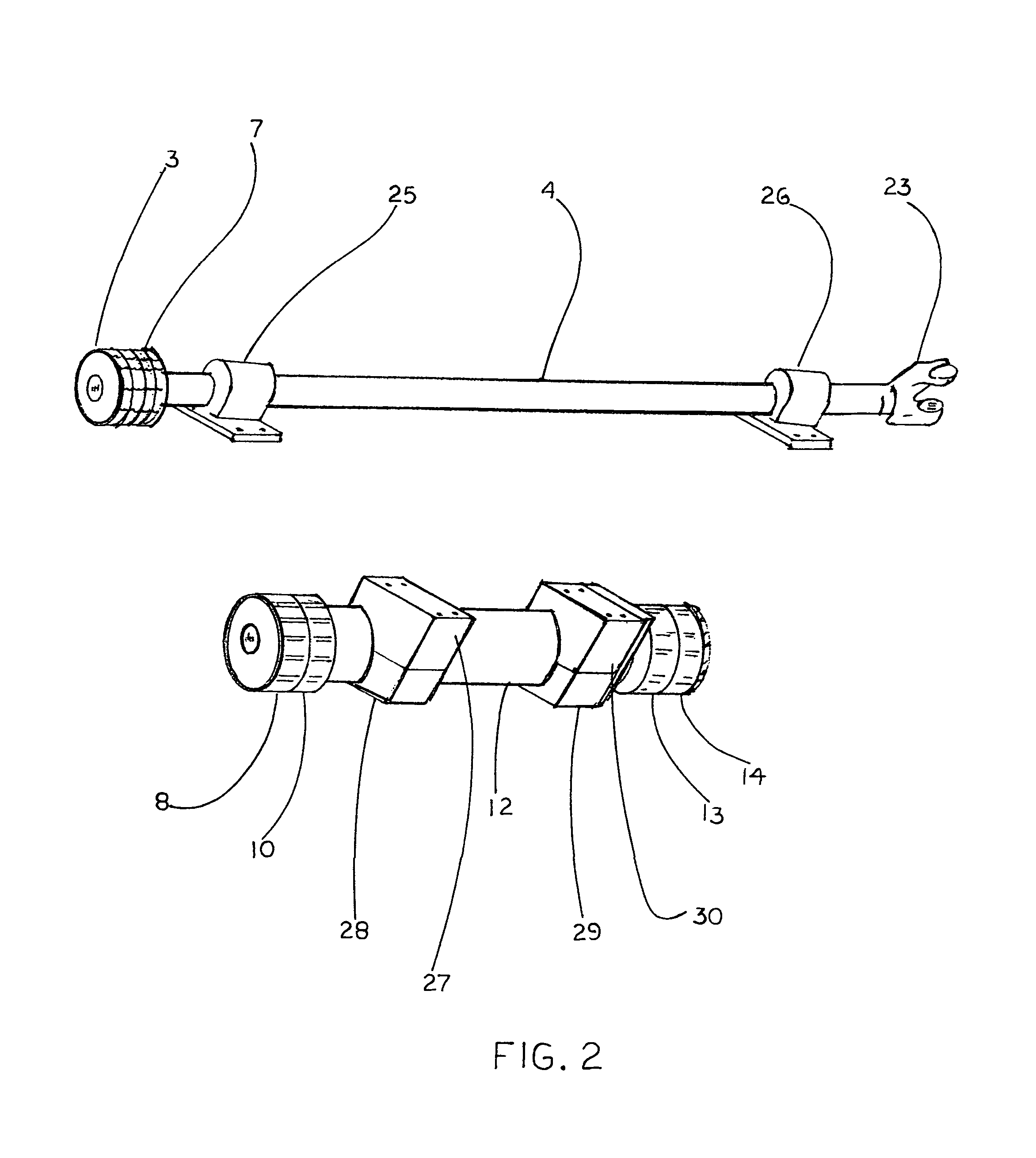
[0063]The throttle position sensor (48) send signal to computer processing unit (41) when receiving input signal from motor rpm sensor (36, 37) connector sensor (45) wheel speed sensor (42) the low traction motor (1) or high traction motor (5) and low electromagnetic clutch (2) or high electromagnetic clutch (6) to energize this rotation is transfer using perpendicular link of belts, chains, or rotation transmission (31, 32) to the connector drive gear (3) this rotation is transfer thru the connector (4) to connector yoke (23) to any flange yoke converting electrical energy into rotation energy to propel the said heavy-duty vehicle. The high electromagnetic clutch (6) and high traction motor (5) will energize to start the vehicle motion. The traction motor (1) and low electromagnetic clutch (2) will energize to maintain vehicle speed. High...


PUM


Abstract

The electric heavy duty vehicle with combination of power storage or energy the on board electric charging and propulsion; the present invention is alternative energy design for electrical vehicles replacing the need for gasoline or other traditional fossil fuel.

Description

[0001]Priority: Related Applications: This application Ser. No. 13 / 815,108 is a continuation-in-part application of application Ser. No. 12 / 804,256, filed Oct. 14, 2010 now abandoned which is a continuation of application 61 / 214,371 filed Sep. 8, 2009.PRIOR ART[0002]There are four methods that show different ideas to heavy duty electric vehicles or hybrid vehicle also several automotive inventions with various mechanisms.[0003]Hydrogen system creates CO2 this is release into the atmosphere under heavy electrical demand the recombination process create water this water will freeze on the road or freezing fuel cells. The fuel cell requires approximately 3,000 times more space than gasoline shown in U.S. Patent Number 20080277175 A1. Internal combustion powered vehicles cost or weight or maintenance needed to alter fossil fuel emissions is high the health of our children exposure to chemical cocktail emissions or green house gas emission and noise pollution are global. Mass transit use...

Claims


Application Information

Patent Timeline
Patent Type & Authority Patents(United States)
IPC IPC(8): B60K1/02B60K1/00B60K1/04B60K17/02B60K17/04
CPCB60K1/00B60K1/04B60K17/02B60K17/04B60L15/2054B60L2200/40B60L2220/42B60L50/51Y02T10/64Y02T10/70Y02T10/72
Inventor MCPARLAND, DAVID BRIAN
Owner MCPARLAND DAVID BRIAN
Learn More