Spherical body polishing apparatus, method for polishing spherical body and method for manufacturing spherical member

a technology for spherical bodies and polishing equipment, which is applied in the direction of mechanical equipment, manufacturing tools, lapping machines, etc., can solve the problems of high hardness and high cost of abrasive grains, and achieve the effect of reducing polishing costs

Inactive Publication Date: 2015-07-28
NTN CORP
View PDF44 Cites 5 Cited by
  • Summary
  • Abstract
  • Description
  • Claims
  • Application Information

AI Technical Summary

Benefits of technology

[0035]As can be clearly seen from the description above, according to the spherical body polishing apparatus, the method for polishing a spherical body and the method for manufacturing a spherical member of the present invention, a spherical body polishing apparatus, a method for polishing a spherical body and a method for manufacturing a spherical member which are capable of reducing polishing costs can be provided.

Problems solved by technology

Accordingly, when the spherical body is made of a high-hardness material, for example, ceramic such as silicon nitride and sialon, an abrasive grain having extremely high hardness and being expensive, such as diamond and CBN (Cubic Boron Nitride) must be used.

Method used


Image

  • Spherical body polishing apparatus, method for polishing spherical body and method for manufacturing spherical member
  • Spherical body polishing apparatus, method for polishing spherical body and method for manufacturing spherical member
  • Spherical body polishing apparatus, method for polishing spherical body and method for manufacturing spherical member

Examples


first embodiment

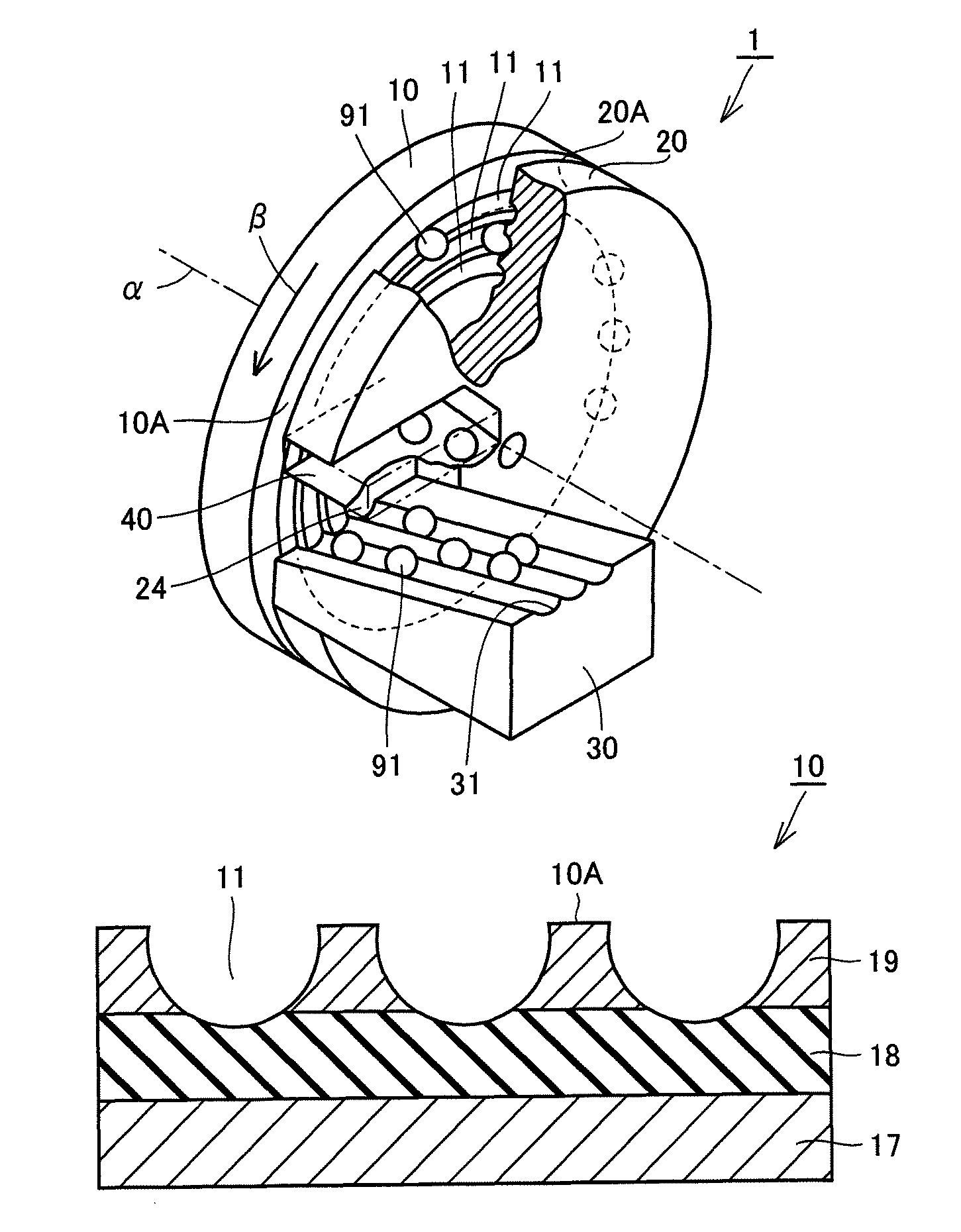
[0042]A first embodiment which is one embodiment of the present invention will be described below. Referring to FIG. 1, a polishing apparatus 1 in the first embodiment includes a rotating disk 10 which is a disk-like surface plate having a rotating disk polishing surface 10A, a fixed disk 20 which is a disk-like surface plate having a fixed disk polishing surface 20A opposed to rotating disk polishing surface 10A, an inlet chute 30 for introducing a material ball 91, which is a spherical body, between rotating disk 10 and fixed disk 20, and an outlet chute 40 for discharging polished material ball 91 out.

[0043]Fixed disk 20 and rotating disk 10 are arranged to leave a predetermined space therebetween such that fixed disk polishing surface 20A and rotating disk polishing surface 10A are parallel to each other and the central axis is in agreement with a rotational axis α. Further, fixed disk 20 is fixed relative to a stand (not shown) holding fixed disk 20, while rotating disk 10 is r...

second embodiment

[0061]Next, a second embodiment which is another embodiment of the present invention will be described. The spherical body polishing apparatus in the second embodiment basically has the same configuration, operates in the same manner and exerts the same effects as those in the first embodiment. The spherical body polishing apparatus in the second embodiment, however, differs in the configuration of the holding layer from that in the second embodiment.

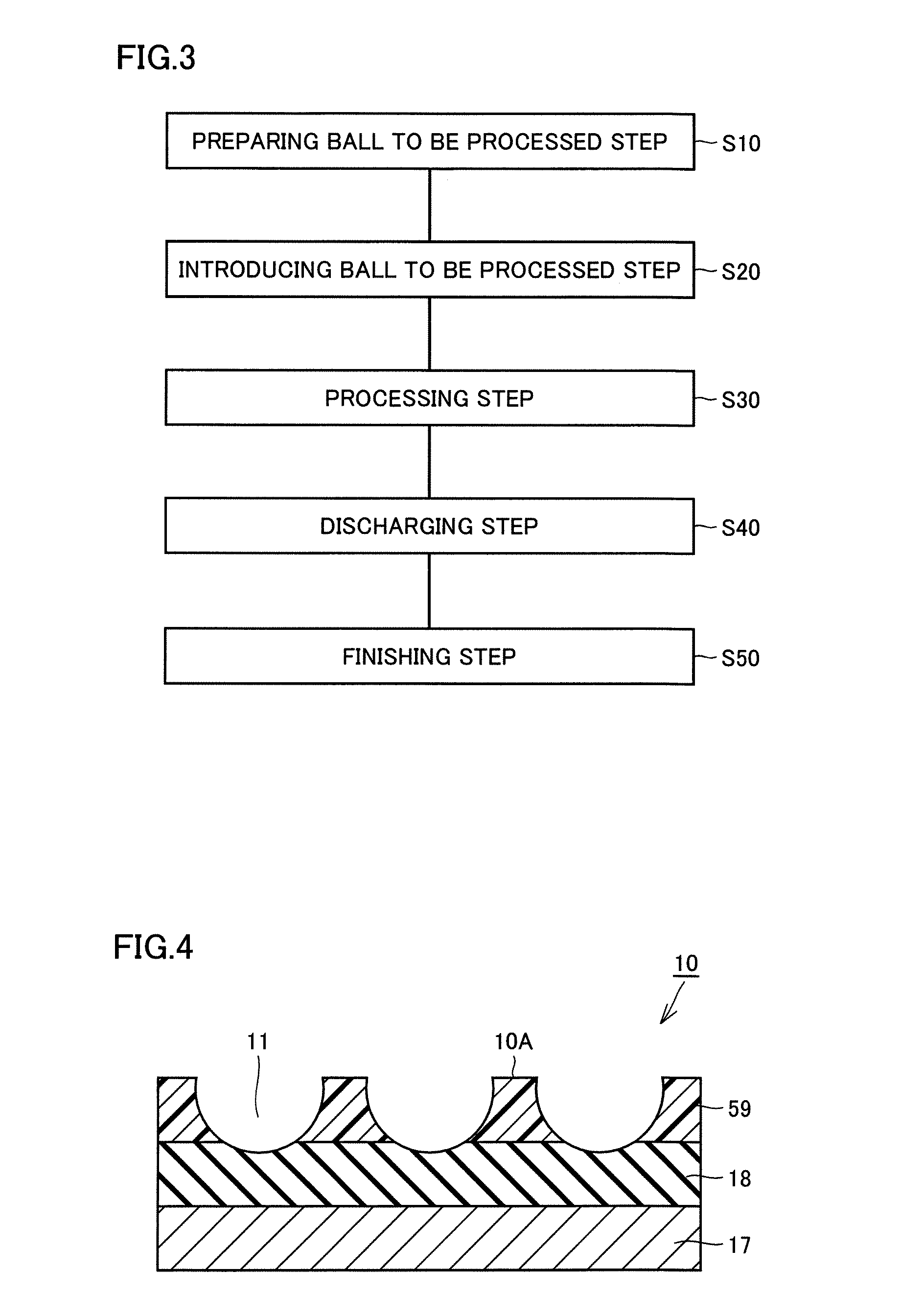
[0062]Referring to FIG. 4, abrasive grain layer 18 of rotating disk 10 in the second embodiment has a configuration in which abrasive grains made of diamonds are bonded together with a bonding agent, as in the first embodiment. Rotating disk 10 in the second embodiment employs a holding layer 59 formed of the bonding agent which bonds abrasive grains together in abrasive grain layer 18, instead of holding layer 19 formed of steel shown in FIG. 2.

[0063]This allows for efficient fabrication of abrasive grain layer 18 and holding layer 59 ...

example 1

[0070]Example 1 of the present invention will be described below. A surface plate having the same configuration as the surface plate described in the second embodiment based on FIG. 4 was fabricated, and a study to confirm a reducing effect on manufacturing costs was conducted. Specifically, an abrasive-grain-containing layer which is a mixture of abrasive grains formed of diamond particles and a metal bond and has a thickness of 3 mm was formed on a surface plate body formed of steel. Further, a bond layer formed of the metal bond and having a thickness of 1.6 mm was formed. Subsequently, calcination was performed to fabricate a member in which an abrasive grain layer and a holding layer were formed on a surface plate body. In the surface of the holding layer-side of the member, groove portions each having a radius of curvature of 4.37 mm and a depth of 2.6 mm was then formed by electric discharge machining. Three groove portions were formed concentrically with radii of 145 mm, 132...


PUM

PropertyMeasurementUnit
thicknessaaaaaaaaaa
thicknessaaaaaaaaaa
depthaaaaaaaaaa

Abstract

A spherical body polishing apparatus capable of reducing polishing costs includes a rotating disk having a rotating disk polishing surface and a fixed disk having a fixed disk polishing surface opposed to the rotating disk polishing surface. The rotating disk polishing surface is capable of relative rotation while keeping being opposed to the fixed disk polishing surface. The rotating disk polishing surface has a groove portion formed therein and extending circumferentially along the rotation. The rotating disk having the groove portion therein includes an abrasive grain layer having a higher hardness than that of a material ball which is a spherical body and a holding layer formed on the abrasive grain layer and having a lower hardness than that of the abrasive grain layer. The groove portion is formed to penetrate the holding layer in a depth direction and to reach the abrasive grain layer.

Description

RELATED APPLICATIONS[0001]This application is the U.S. National Phase under 35 U.S.C. §371 of International Application No. PCT / JP2009 / 066503, filed on Sep. 24, 2009, which in turn claims the benefit of Japanese Application No. 2008-258419, filed on Oct. 3, 2008, the disclosures of which Applications are incorporated by reference herein.TECHNICAL FIELD[0002]The present invention relates to a spherical body polishing apparatus, a method for polishing a spherical body and a method for manufacturing a spherical member, and more particularly to a spherical body polishing apparatus, a method for polishing a spherical body and a method for manufacturing a spherical member which are capable of reducing polishing costs.BACKGROUND ART[0003]A manufacturing process of a spherical member to be used as, for example, a rolling element of a rolling bearing or a valving element of a ball valve often includes the step of polishing the surface of a spherical body. To this step of polishing a spherica...

Claims


Application Information

Patent Timeline
Patent Type & Authority Patents(United States)
IPC IPC(8): B24B11/06B24B37/025B24D7/18F16C33/32B24B37/02B24D3/34B24D7/00
CPCB24B37/025B24B11/06B24D7/18F16C33/32F16C2206/40
Inventor TANAKA, YUTAKAMURAMATSU, KATSUTOSHI
Owner NTN CORP
Why Eureka
Try Eureka