Self-charging electric vehicle and aircraft and wireless energy distribution system

a wireless energy distribution system and electric vehicle technology, applied in the direction of electric vehicle charging technology, charging stations, transportation and packaging, etc., can solve the problems of increasing costs, ev more expensive than gasoline cars, and preventing the company producing the devices or cars from achieving optimal design, etc., to minimize electrical resistance, loss and heat generation, and increase the power generation. , the effect of increasing the distan

Inactive Publication Date: 2015-07-28
PARADIGM SHIFTING SOLUTIONS LLC
View PDF8 Cites 9 Cited by
  • Summary
  • Abstract
  • Description
  • Claims
  • Application Information

AI Technical Summary

Benefits of technology

[0009]The present invention enables fast top off charges to be done during EV transport or during short stops at multiple locations which allows for EV vehicles to have full range with much smaller batteries in the EV and in EV public transport systems. This new configuration drastically reduces the cost of such vehicles making them more affordable and available to the general public. This invention also combines multiple forms of storage and batteries and power such as alternating current (AC) and direct current (DC) in a single system with different frequencies and modulations as well as different storage materials and components for each stage of the power collection from the local grid, AC or DC sources. Resonant tuned shaped alternating or pulsed magnetic fields enable efficient wireless transfer, tuned transmission and receiving coils as well as passive tuned coils and elements designed for optimal reception, tuning, tunneling and absorption of EMF into AC and multi stage electrical storage on board the EV to maximize and optimize the speed and volume of energy transferred. Different type of batteries and capacitors can be combined into structures to provide better protection for the encasement and safety of the entire EV storage solution. For example the outside of the battery may be made of nano tubes and configured to act as a super capacitor connected to the inside batteries and take advantage of the strength of the nano material casing to contain many smaller batteries made of more volatile materials such as Lithium.
[0034]According to an aspect of the invention, the inventive system provides: (1) A charge and discharge system for electrical vehicles comprised of multiple types of electricity storage systems which enables fast transfer, absorption and extraction of electrical charge; (2) Control systems which communicate and arrange the transfer of charge between such different storage systems to maximize the rate of absorption and transfer of electric power but minimize any long term damage to the devises and maximize the life expectancy and number of cycles such systems can manage over time; and (3) A design of an electrical vehicle power storage unit which uses carbon nano tubes configured as a container and which holds other types of storage units and act as a super capacitor connected to such other storage units.

Problems solved by technology

For many consumer devices and Electrical Vehicles (EV) the size, weight and cost of the large battery is a major design and cost problem which prevents the company producing the devices or cars from achieving the optimal design and performance characteristics they would like.
The added cost makes EV more expensive than gasoline cars and require high maintenance for both motors.
While many attempts are known in the art for wireless charging all such innovations require very small gap of no more than few inches or touch between the transmitting coil and receiving coils to transfer power from the source to a device and they do not solve the issue of rapid transfer of vast amounts of energy or the automated configuration, security, authentication and conditioning of the power to the specific device which needs the charge.

Method used


Image

  • Self-charging electric vehicle and aircraft and wireless energy distribution system
  • Self-charging electric vehicle and aircraft and wireless energy distribution system
  • Self-charging electric vehicle and aircraft and wireless energy distribution system

Examples


Embodiment Construction

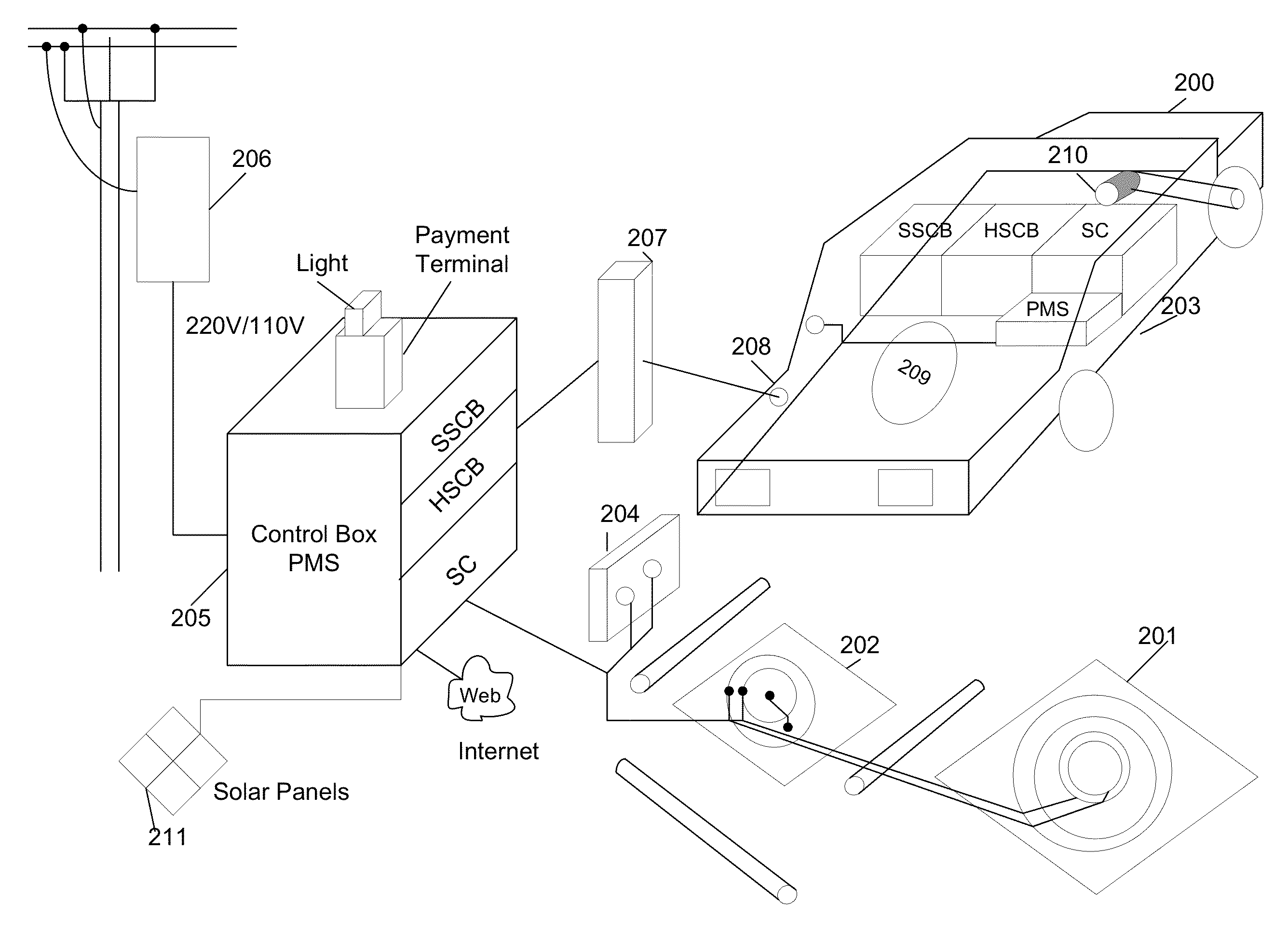
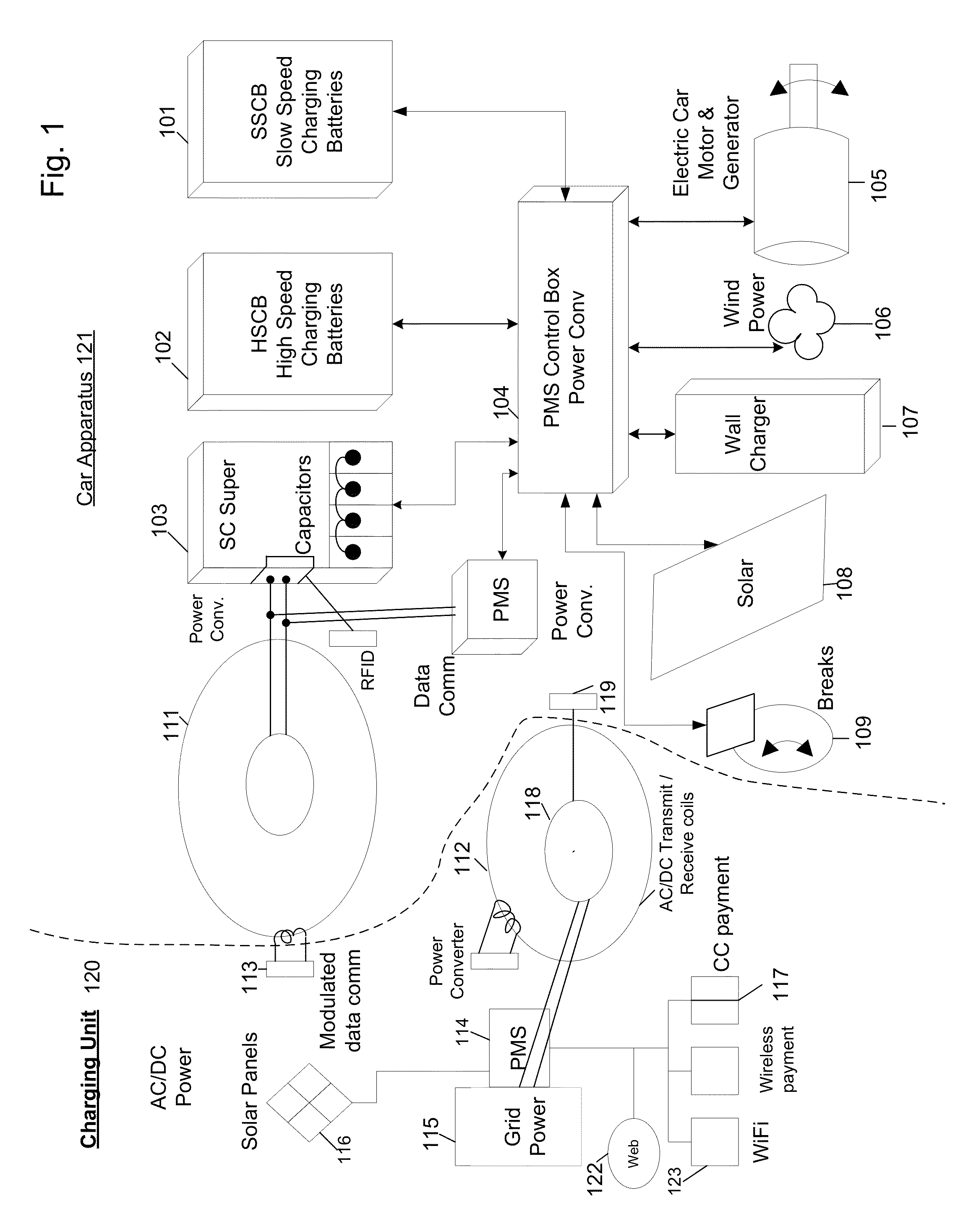
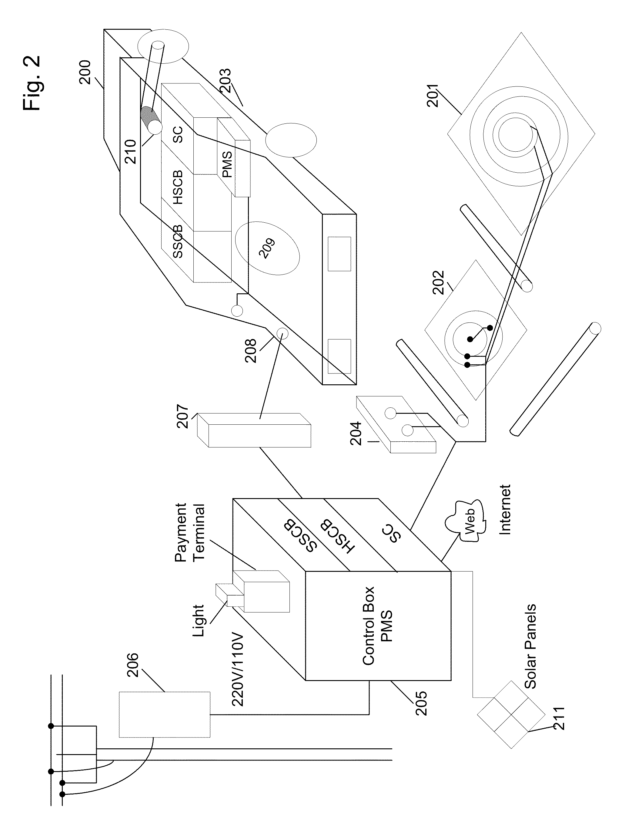
[0040]FIG. 1 illustrates the charging unit 120 and the car apparatus 121 and how they interact with each other to provide ultra fast charging and top off services. The PMS 114 is connected to grid power 115 and other power sources such as solar panels 116 and coil 112 and 118 as well as wireless sensors 117 and the web 122. The charging unit 120 can communicate with car 121 via coils 112 and 118 or via wireless connection 123 or via internet 122 or other wireless device.

[0041]The electric power is conditioned and collected by the PMS 114 from all sources and is stored in super caps and batteries connected to PMS 114 so it could be discharged at a very high rate that is much higher than the transfer rate the grid or other power sources can deliver. When a car aligns its receiving coil 111 and signals to the PMS the amount of time, power and type of systems it has on board the PMS 114 calculates the optimal configuration and a transfer takes place and the power is directed by the PMS ...


PUM


Abstract

A system and method to provide fast charge and discharge of electrical power without wires between two elements configured to have resonant tuned coils and circuits. The coils are energized by a power source that includes super capacitors, fast charging batteries and oscillating power management system.

Description

RELATED APPLICATIONS[0001]This application claims priority from U.S. Provisional Patent Application Ser. No. 61 / 798,240 filed on Mar. 15, 2013, and is a continuation-in-part of U.S. patent application Ser. No. 12 / 679,060 filed on Mar. 19, 2010, and is a continuation-in-part of U.S. patent application Ser. No. 12 / 229,706, filed on Aug. 26, 2008, all of which are incorporated herein by reference in their entirety.BACKGROUND OF THE INVENTION[0002]Millions of electrical vehicles and other electric transportation systems are coming to market which require constant charging. All such devices have large slow charging batteries and other storage devices of electrical charge which need to be plugged in to DC or AC power sources to be recharged. For some of these a slow charge of several hours is required to complete charge the slow-charging NiMH or Li-ion or Led acid batteries. For many consumer devices and Electrical Vehicles (EV) the size, weight and cost of the large battery is a major de...

Claims


Application Information

Patent Timeline
Patent Type & Authority Patents(United States)
IPC IPC(8): H02J7/00B60L11/18H02J7/14
CPCB60L11/182B60L11/185B60L11/1842B60L11/1846B60L2230/22B60L2230/24B60L2230/30B60L2230/32Y02E60/721Y02T10/7005Y02T10/7088Y02T90/121Y02T90/122Y02T90/128Y02T90/14Y02T90/169Y04S10/126Y04S30/14B60L55/00B60L53/65B60L53/11B60L53/51B60L53/52B60L53/53B60L53/55B60L53/126Y02E60/00Y02T10/7072Y02T10/70Y02T90/12Y02T90/167B60L53/12
Inventor MASHINSKY, ALEXMASHINSKY, DAVIDMASHINSKY, RENA
Owner PARADIGM SHIFTING SOLUTIONS LLC
Why Eureka
Try Eureka