
Fluid working machines and methods

a working machine and working method technology, applied in mechanical equipment, water supply installation, gas/liquid distribution and storage, etc., can solve the problems of reducing efficiency, increasing noise, and expensive performance limiting components of electric controllable valves, so as to facilitate the opening of primary low-pressure valves, reduce the and reduce the effect of pressure within the working chamber

Active Publication Date: 2015-07-28
DANFOSS PAUER SOLYUSHENS APS
View PDF43 Cites 5 Cited by
  • Summary
  • Abstract
  • Description
  • Claims
  • Application Information

AI Technical Summary

Benefits of technology

The patent describes a device that helps improve the performance and efficiency of a fluid working machine by using a primary low pressure valve and a secondary low pressure port to supply fluid into or out of a working chamber. This leads to better fill or exhaust characteristics, reduced noise, improved efficiency, and increased operating life of the machine. The secondary low pressure port also helps release pressurized fluid to open the primary low pressure valve.

Problems solved by technology

Accordingly, the electronically controllable valves are an expensive and performance limiting component of such fluid working machines and it would be desirable to reduce one or more of the demands made on the electronically controllable valves.
In particular, a significant technical problem, which determines the specification of electronically controllable valves for a particular application, arises when fluid flows into a working chamber of a pump from a low pressure manifold during an expansion stroke of a working chamber.
Where the fluid flowing into the working chamber is a liquid, it is subject to cavitation, which increases noise, reduces efficiency by requiring a pressure difference across the poppet valve, and leads to damage to the machine.
A different problem applies during the contraction stoke of a working chamber in a motor, when fluid flows out to a low pressure manifold, where an increased pressure drop causes inefficiency, and where the poppet valve may be inadvertently closed causing possible damage to the valve and inadvertent pumping.
However, larger electronically controllable valves are more expensive and there can be a trade off in performance characteristics.
For example, larger electronically controllable valves may open and close more slowly than smaller valves or use more electrical power, forcing compromises to be made.
However, it can take a significant period of time for the pressure of the fluid trapped within the working chamber to drop to a sufficiently low value, for several reasons.
Firstly, the rate of change of working chamber volume decreases towards the end of the expansion stroke in most fluid working machines.
Secondly, the variation in pressure of the fluid trapped within the working chamber is not a linear function of the volume of the working chamber, in the case of many commonly used hydraulic fluids.
This delay can reduce the efficiency of the fluid working motor.
Indeed, malfunctions can arise if the pressure within the working chamber does not drop to a sufficiently low value to enable the opening of the low pressure valve, for example on start-up, or when operating in especially high or low temperature conditions.

Method used


Image

  • Fluid working machines and methods
  • Fluid working machines and methods
  • Fluid working machines and methods

Examples


example one

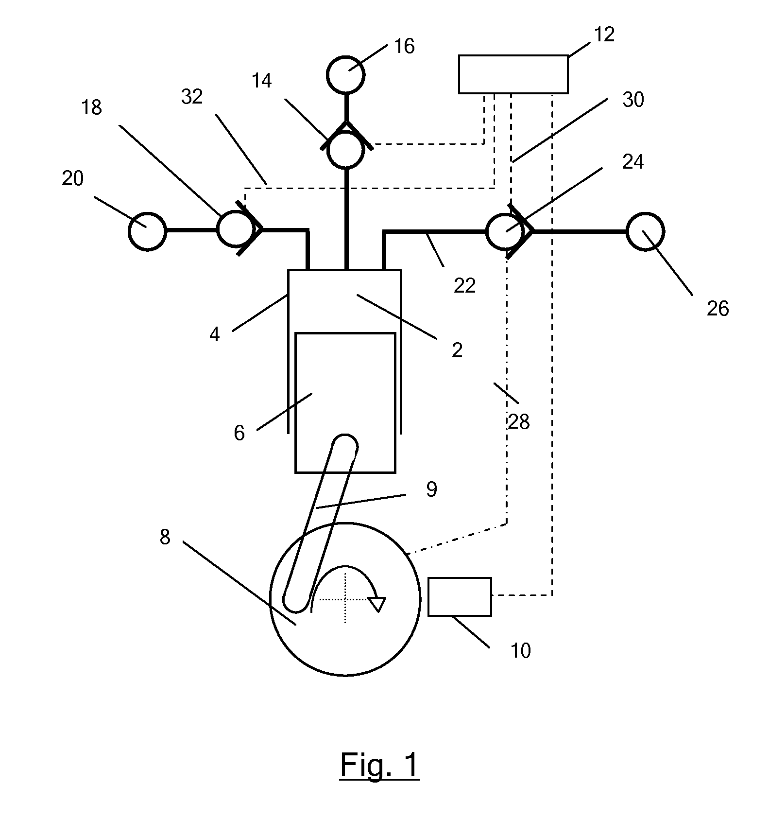
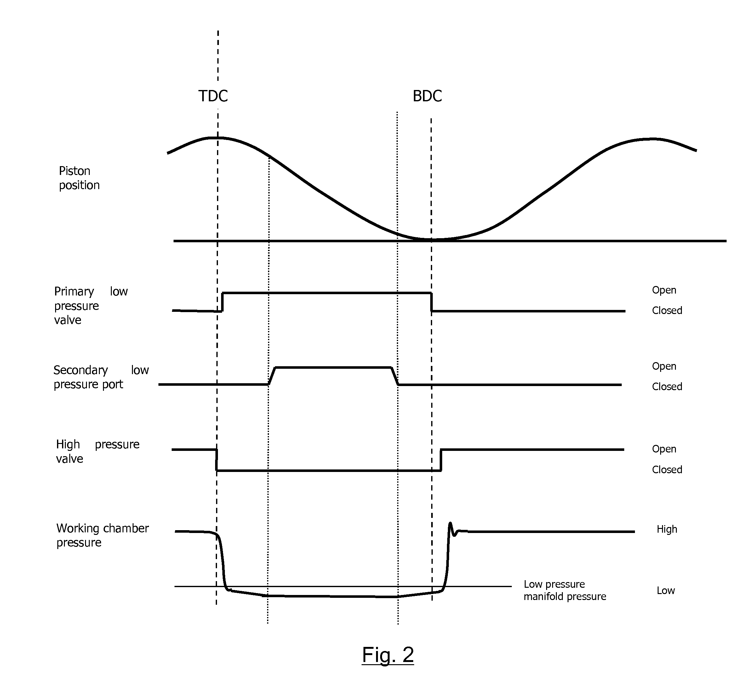
[0100]In a first example, a fluid working machine in the form of a hydraulic pump includes a plurality of working chambers. FIG. 1 illustrates an individual working chamber 2 which has a volume defined by the interior surface of a cylinder 4 and a piston 6 which is driven from a crankshaft 8 by a crank mechanism 9 and which reciprocates within the cylinder to cyclically vary the volume of the working chamber. A shaft position and speed sensor 10 determines the instantaneous angular position and speed of rotation of the shaft, and transmits shaft position and speed signals to a controller 12, which enables the controller to determine the instantaneous phase of the cycles of each individual working chamber. The controller is typically a microprocessor or microcontroller which executes a stored program in use.

[0101]The working chamber comprises a primary low pressure valve in the form of an electronically actuatable face-sealing poppet valve 14, which faces inwards toward the working c...

example two

[0110]In a second example, the fluid working machine is operable to function as either a motor or a pump. The structure of the second example fluid working machine also corresponds to the structure illustrated in FIG. 1. In this embodiment, the primary low pressure valve functions as a net source of fluid or a net sink in pumping or motoring mode respectively. The secondary low pressure port also functions as either a net source of fluid or net sink respectively, and the high pressure valve functions as either a net sink of fluid or net source respectively. A single low pressure manifold functions as either a net source of fluid, in pumping mode, or as a sink of fluid, in motoring mode, and the high pressure manifold functions as either a sink of fluid, in pumping mode, or as a source of fluid, in motoring mode. During idle strokes in which a working chamber is kept in fluid communication with the low pressure manifold, neither manifold functions as a net source or sink of fluid.

[01...

example three

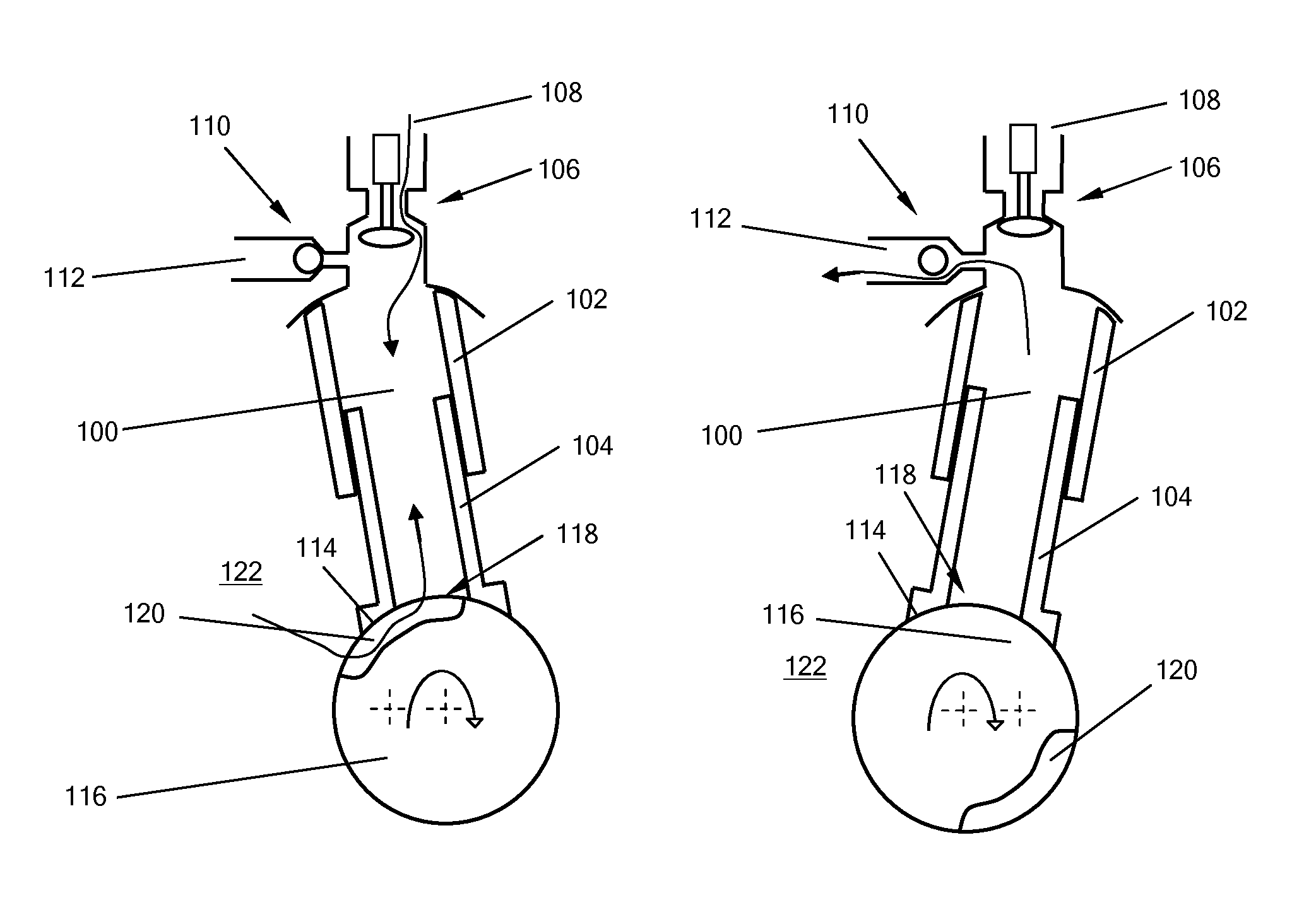
[0114]In a third example embodiment a fluid working machine in the form of a hydraulic radial piston pump uses a slotted crankshaft to provide a secondary low pressure port. FIG. 3 illustrates fluid flow through an individual working chamber 100, defined by the interior surface of a cylinder 102 and reciprocating hollow piston 104, part way through an expansion stroke.

[0115]The working chamber has a primary low pressure valve 106, in the form of an electronically controllable poppet valve, which is openable and closable to bring the working chamber into and out of fluid communication with a first low pressure manifold 108. A high pressure valve in the form of a pressure-operable discharge valve 110 is openable and closable to bring the working chamber into and out of fluid communication with a high pressure manifold 112. The base 114 of the piston is in sliding contact with a crankshaft eccentric 116. An aperture 118 in the base of the piston functions as a secondary low pressure po...


PUM


Abstract

A fluid working machine comprises a controller and a working chamber of cyclically varying volume having an electronically controllable primary low pressure valve and a secondary low pressure port associated therewith, each of which is openable and closable in phased relation to cycles of working chamber volume to bring the working chamber into fluid communication with a low pressure manifold. At least the primary low pressure valve is under the active control of the controller to enable the controller to determine the net displacement of fluid by the working chamber on a cycle by cycle basis. The primary low pressure valve and the secondary low pressure port are openable concurrently and in parallel during a portion of at least some cycles of working chamber volume, including at the point in the expansion or contraction stroke where the rate of change of volume of the working chamber is greatest.

Description

[0001]This application is the U.S. national phase of International Application No. PCT / GB2009 / 050714 filed 22 Jun. 2009, which designated the U.S. and claims priority to GB Application No. 0811385.4 filed 20 Jun. 2008, the entire contents of each of which are hereby incorporated by reference.FIELD OF THE INVENTION[0002]The invention relates to the field of fluid working machines, particularly fluid working machines which comprise at least one working chamber of cyclically varying volume, in which the net displacement of fluid through the or each working chamber is regulated by at least one electronically controllable valve, on a cycle by cycle basis, to determine the net throughput of fluid through the or each working chamber.[0003]Some embodiments of the invention relate to a method of supplying fluid to, or receiving fluid from, a working chamber of a fluid working machine. Some embodiments of the invention aim to facilitate the opening of an electronically controllable valve duri...

Claims


Application Information

Patent Timeline
Patent Type & Authority Patents(United States)
IPC IPC(8): F04B35/04F01B15/06F04B7/00F01B25/10F04B49/24
CPCF04B7/0076F01B15/06F01B25/10F04B7/0057F04B49/24Y10T137/0324F04B7/00
Inventor STEIN, UWE BERNHARD PASCALCALDWELL, NIALL JAMES
Owner DANFOSS PAUER SOLYUSHENS APS
Learn More