Damping circuit for an energy storage device and method for damping oscillations of the output current of an energy storage device

a technology of energy storage device and output current, which is applied in the direction of dynamo-electric converter control, greenhouse gas reduction, battery/fuel cell control arrangement, etc., can solve the problems of reducing the power of the entire energy supply string, the failure of the entire system, so as to reduce the requirement, reduce the complexity, and reduce the cost

Active Publication Date: 2015-07-28
ROBERT BOSCH GMBH
View PDF3 Cites 1 Cited by
  • Summary
  • Abstract
  • Description
  • Claims
  • Application Information

AI Technical Summary

Benefits of technology

[0012]In accordance with a further embodiment, the present invention provides a method for damping oscillations of the output current of an energy storage device, which has one or more energy storage modules, which are connected in series in one or more energy supply strings, said energy storage modules comprising at least one energy storage cell and a coupling device having a multiplicity of coupling elements, which coupling device is designed to connect the energy storage cell selectively into the respective energy supply string or to bridge said energy storage cell. The method comprises the steps of detecting an output current of the energy supply strings or the energy storage device, generating an output current signal which is dependent on the detected output current, applying closed-loop control to the output current signal to adjust it to a setpoint current signal, outputting a current control signal corresponding to the closed-loop control, generating a compensation current, which compensates for fluctuations in the output current of the energy storage device, and feeding the compensation current into the second winding of a transformer, which has a first winding, which is coupled to an output connection of the energy storage device, and a second winding, which is galvanically isolated from the first winding.
[0014]As a result of this damping, on-board power supply system resonances can be damped without any additional losses in the power path. By virtue of inherent closed-loop control via the current feedback loop, it is advantageously possible to match the damping to the position of the resonance frequency and the magnification factor of the resonant circuit, irrespective of the instantaneous operating state of the energy storage device. In particular, measurement of the resonant frequency of the energy storage device is no longer necessary. Changes which can occur, for example, owing to aging or changes in the system topology, for example owing to longer high-voltage lines, during operation of the energy storage device are also automatically and flexibly compensated for by the damping circuit.
[0015]By virtue of the active closed-loop control, a degree of damping can advantageously be selected by an adjustable frequency range. The energy storage device can in this case be operated in the conventional manner without load current-conducting components needing to be clocked variably in a manner subject to losses.
[0016]The damping circuit can advantageously be implemented completely in the low-voltage range by the galvanic decoupling, as a result of which soft switching and a single feed from a 12 volt power supply system is possible. The design and control parameters for the damping circuit are in this case independent of the instantaneous value for an intermediate circuit capacitor connected to the energy storage device.
[0017]The damping circuit can advantageously be used in a conventional on-board power supply system. In addition, already existing components, such as a current-limiting inductor, for example, can be used in the configuration of the damping circuit, which results in reduced costs, reduced complexity and reduced requirement in terms of installation space.
[0018]In accordance with one embodiment of the damping circuit according to the invention, the damping circuit can furthermore comprise a bandpass filter, which is coupled between the current detection device and the closed-loop control circuit and which is designed to filter frequency components of the output current signal outside a predeterminable frequency range. This advantageously enables damping, as required, in the critical resonant frequency range, with the result that no damping and therefore no unnecessary consumption of resources takes place in uncritical ranges. In particular in frequency ranges in which high powers would otherwise need to be applied for active damping, but damping of the current ripple is not necessarily required at all, this can result in an increase in the efficiency of the damping circuit.
[0019]In accordance with a further embodiment of the damping circuit according to the invention, the current detection device can be designed to detect a difference between the output current of the energy storage device and the output current of a DC voltage intermediate circuit, which is connected to the energy storage device. This provides the advantage that it is possible to dispense with a particularly low-induction connection of a current detection device to the intermediate circuit capacitor.
[0012]In accordance with a further embodiment, the present invention provides a method for damping oscillations of the output current of an energy storage device, which has one or more energy storage modules, which are connected in series in one or more energy supply strings, said energy storage modules comprising at least one energy storage cell and a coupling device having a multiplicity of coupling elements, which coupling device is designed to connect the energy storage cell selectively into the respective energy supply string or to bridge said energy storage cell. The method comprises the steps of detecting an output current of the energy supply strings or the energy storage device, generating an output current signal which is dependent on the detected output current, applying closed-loop control to the output current signal to adjust it to a setpoint current signal, outputting a current control signal corresponding to the closed-loop control, generating a compensation current, which compensates for fluctuations in the output current of the energy storage device, and feeding the compensation current into the second winding of a transformer, which has a first winding, which is coupled to an output connection of the energy storage device, and a second winding, which is galvanically isolated from the first winding.
[0021]In accordance with a further embodiment of the damping circuit according to the invention, the first winding of the transformer can comprise an output-side current limitation inductor of the energy storage device. This has the advantage that the current-limiting inductor already provided in any case can be provided for a dual use in order to save on installation space and components.
[0022]In accordance with a further embodiment of the damping circuit according to the invention, the compensation current generation device can have an H-bridge circuit with in each case two switching devices in each of the bridge branches. This provides the advantage that low-resistance low-voltage switches can be used for the switching device which can be used as soft-switching full bridge to implement active closed-loop control of damping with very low losses.
[0024]In accordance with one embodiment of the system according to the invention, the system can furthermore have a DC voltage intermediate circuit, which is coupled to output connections of the energy storage device. Advantageously, the system can furthermore comprise an inverter, which is coupled to the DC voltage intermediate circuit, and an electric machine, which is coupled to the inverter. The inverter can be designed to convert the voltage of the DC voltage intermediate circuit into an input voltage for the electric machine. This is particularly advantageous since the system comprising the inverter and the electric machine, as variable current source, can feed back currents with frequency-dependent fluctuations into the energy storage device via the DC voltage intermediate circuit. These frequency-dependent fluctuations can be damped particularly effectively via the damping circuit.
[0024]In accordance with one embodiment of the system according to the invention, the system can furthermore have a DC voltage intermediate circuit, which is coupled to output connections of the energy storage device. Advantageously, the system can furthermore comprise an inverter, which is coupled to the DC voltage intermediate circuit, and an electric machine, which is coupled to the inverter. The inverter can be designed to convert the voltage of the DC voltage intermediate circuit into an input voltage for the electric machine. This is particularly advantageous since the system comprising the inverter and the electric machine, as variable current source, can feed back currents with frequency-dependent fluctuations into the energy storage device via the DC voltage intermediate circuit. These frequency-dependent fluctuations can be damped particularly effectively via the damping circuit.

Problems solved by technology

A series circuit comprising a plurality of battery modules is associated with the problem that the entire string fails when a single battery module fails.
Such a failure of the energy supply string can result in failure of the entire system.
Furthermore, temporarily or permanently occurring reductions in power of a single battery module can result in reductions in power in the entire energy supply string.
This means that, when the energy storage device is coupled to a load acting as variable current source, such as an inverter and an electric machine connected downstream of the inverter, for example, undesired resonances can occur.

Method used


Image

  • Damping circuit for an energy storage device and method for damping oscillations of the output current of an energy storage device
  • Damping circuit for an energy storage device and method for damping oscillations of the output current of an energy storage device
  • Damping circuit for an energy storage device and method for damping oscillations of the output current of an energy storage device

Examples


Embodiment Construction

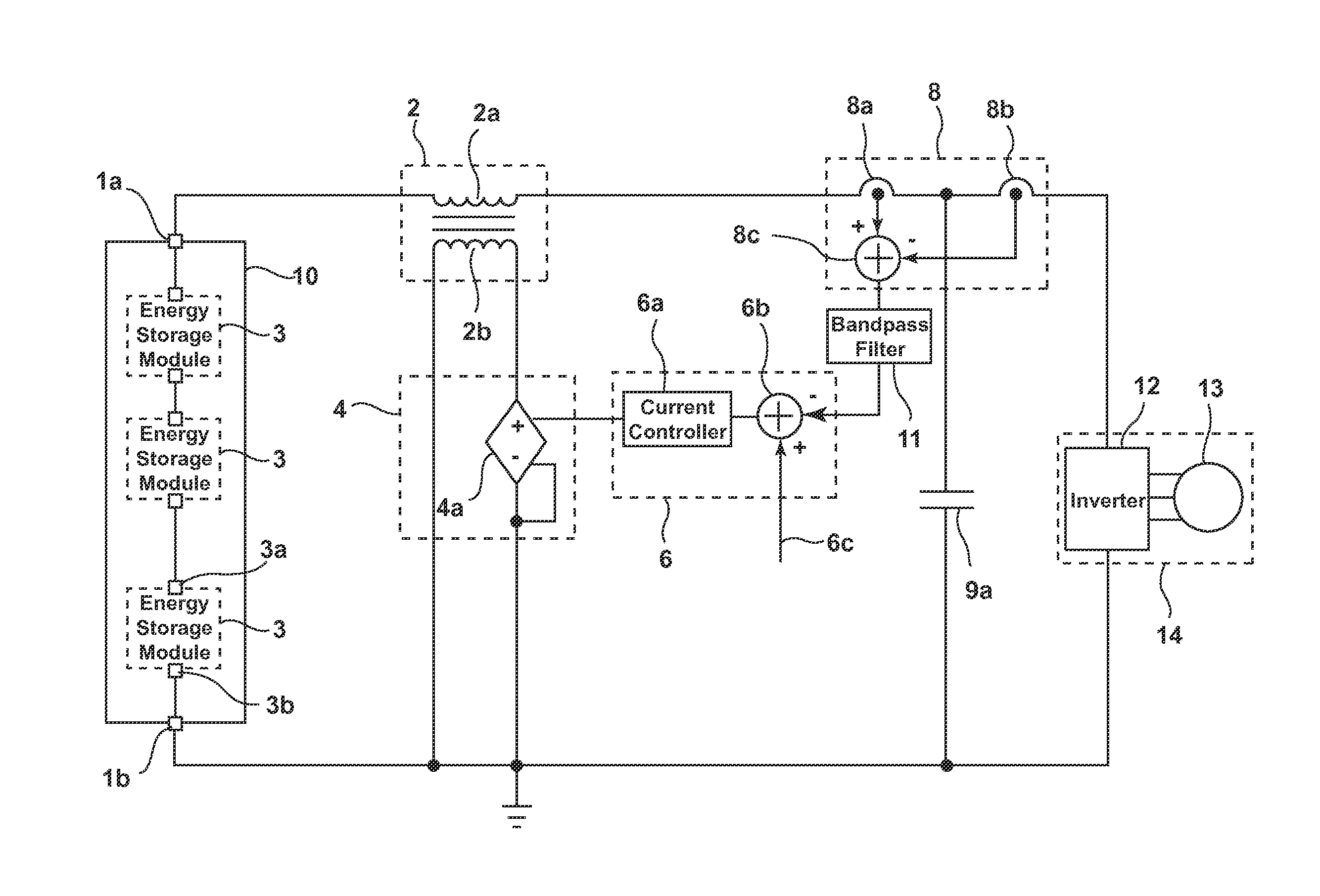
[0032]FIG. 1 shows a system which comprises an energy storage device 10 for providing a supply voltage by energy storage modules 3 connected in series in an energy supply string between two output connections 1a, lb of the energy storage device 10. The energy storage device 10 can alternatively also have a plurality of energy supply strings connected in parallel. The energy storage device 10 acts as current source of a variable output current owing to the actuation of the energy storage modules 3.

[0033]The energy storage device 10 can in this case be coupled to an input connection of a DC voltage intermediate circuit 9a via a storage inductance 2a at the output connection 1a of the energy storage device 10. The storage inductance 2a can be implemented, for example, by a concentrated component, such as a current-limiting inductor, or a plurality of distributed components. Alternatively, parasitic inductances of the energy storage device 10 can also be used as storage inductance 2a. B...


PUM


Abstract

A damping circuit for an energy storage device. The damping circuit comprises a current detection device designed to detect an output current of energy supply strings or the energy storage device and to generate an output current signal dependent on the output current. The damping circuit also includes a closed-loop control circuit coupled to the current detection device. The closed-loop control circuit designed to adjust the output current signal to a setpoint current signal and to output a corresponding current control signal. A first winding of a transformer is coupled to an output connection of the energy storage device. A second winding is galvanically isolated from the first winding. A compensation current generation device is coupled to the closed-loop control circuit, and is designed to feed a compensation current into the second winding of the transformer depending on the current control signal.

Description

BACKGROUND OF THE INVENTION[0001]The invention relates to a damping circuit for an energy storage device and to a method for damping oscillations of the output current of an energy storage device, in particular for battery converter circuits for supplying voltage as a variable current source for loads occurring such as, for example, electric machines in drive systems of electrically operated watercraft or land vehicles.[0002]It would appear that, in the future, electronic systems which combine novel energy storage technologies with electric drive technology will be used increasingly both in stationary applications, such as wind turbines or solar power installations, for example, and in vehicles such as hybrid or electric vehicles.[0003]In order to feed alternating current into an electric machine, a DC voltage provided by a DC voltage intermediate circuit is conventionally converted into a three-phase AC voltage via a converter in the form of a pulse-controlled inverter. The DC volt...

Claims


Application Information

Patent Timeline
Patent Type & Authority Patents(United States)
IPC IPC(8): H02J3/00
CPCH02J3/005Y02E10/76Y02E70/30H02M1/15B60L2200/32B60L2220/12B60L2220/14B60L2220/16B60L2220/18B60L2240/545B60L2240/547B60L2240/549B60L50/51B60L58/21Y02T10/70
Inventor KESSLER, MARTIN
Owner ROBERT BOSCH GMBH
Why Eureka
Try Eureka