Preamplifier for charged particle detection

a technology for amplifying particles and amplifying tubes, which is applied in the field of preamplifying for charged particles to achieve the effect of increasing the complexity of the apparatus (logic)

Active Publication Date: 2015-08-04
THERMO FISHER SCI BREMEN
View PDF14 Cites 0 Cited by
  • Summary
  • Abstract
  • Description
  • Claims
  • Application Information

AI Technical Summary

Benefits of technology

[0008]This preamplifier uses the feed-forward stage to provide compensation for the artefacts that are introduced into the isolated signal, especially when that signal is generated using a transformer. By generating a compensation signal that mirrors the overshoot or undershoot effects and therefore creates pulse shaping, this distortion is removed after the main amplification. The compensation signal may be a proportional modified copy of the isolated signal from the detection electrode. Advantageously, the feed-forward stage takes an amplified version of the isolated signal as its input, rather than the isolated signal itself. This means that weak signals are amplified before compensation and makes it easier to discriminate (in a subsequent stage) between overshoot or undershoot effects and weak pulses. Moreover, the main amplification stage may be used to provide inherent stability to the preamplifier. This may thereby avoid any condition or state leading to oscillation, possibly due to superimposing the compensation signal on the amplified isolated signal.
[0012]In the preferred embodiment, the main amplification stage comprises a non-inverting amplifier configuration. This may comprise an operational amplifier with the isolated signal provided to its non-inverting input, a first resistance coupled between its inverting input and a reference voltage and a second resistance coupled between its output and its inverting input. Beneficially, a capacitance may also be provided between the output of the operational amplifier and its inverting input. This may provide stability, in particular to compensate for a phase margin of the operational amplifier.
[0013]Advantageously, the isolated signal comprises a pulse. Then, the feed-forward stage may be configured to generate the compensation signal in proportionality to a magnitude and width of the pulse. In particular, the feed-forward stage and the output may be configured to provide the output signal such that it comprises a pulse corresponding with the pulse of the isolated signal. Then, the pulse of the output signal may be substantially no wider than the pulse of the isolated signal. Widening the pulse may cause any adjacent pulses to be less discernable. Moreover, it may increase the complexity of the apparatus (logic) used to generate the mass spectrum and compensate for “dead time” of the mass spectrometer.
[0015]Beneficially, the integrator (integrative signal-shaping circuit) is further configured to comprise an additional decay component. The decay component may create an exponential tailing effect that is quite long compared to the rise time of the integrator. Advantageously, the additional decay component comprises one or more diodes, beneficially forward-biased. Optionally, the one or more diodes comprise a silicon diode and preferably a PIN diode. The PIN diode may create the exponential tailing effect noted above, although other diodes may be used alternatively. In the preferred embodiment, the integrator comprises an amplifier with negative feedback, particularly an inverting amplifier. The capacitance and the decay component are beneficially provided in the feedback loop. The capacitance provides the integration (low-pass filtering) effect. This may further smooth the output signal and lower noise due to interference.
[0018]The compensated isolated signal may be generated by the combination, specifically superposition, of the amplified isolated signal and the compensation signal. Preferably, the output of the preamplifier comprises a summing junction, configured to receive the amplified isolated signal through a first resistance, to receive the compensation signal through a second resistance and to provide the output signal by summing the received signals. Advantageously, the first and second resistances are selected in order to cause the summation of the amplified isolated signal and the compensation signal to correct the overshoot or undershoot effects present in the isolated signal.

Problems solved by technology

However, such devices may also be responsible for introducing the overshoot or undershoot effects that the preamplifier is intended to correct.

Method used


Image

  • Preamplifier for charged particle detection
  • Preamplifier for charged particle detection
  • Preamplifier for charged particle detection

Examples


Embodiment Construction

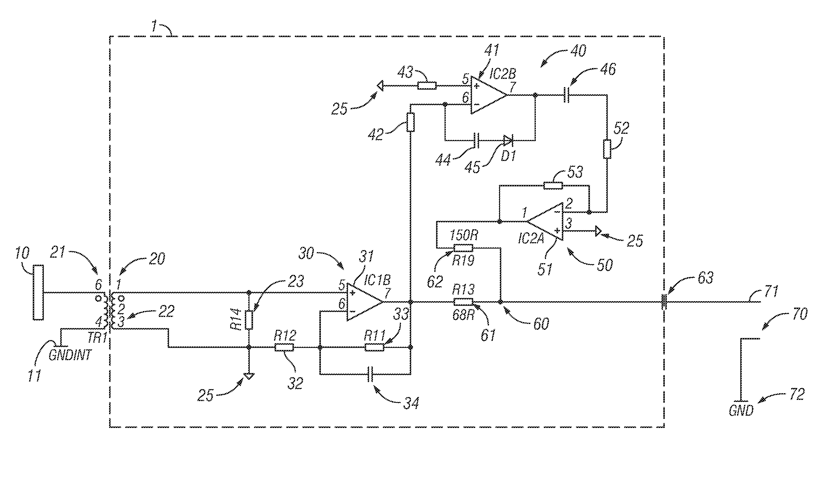
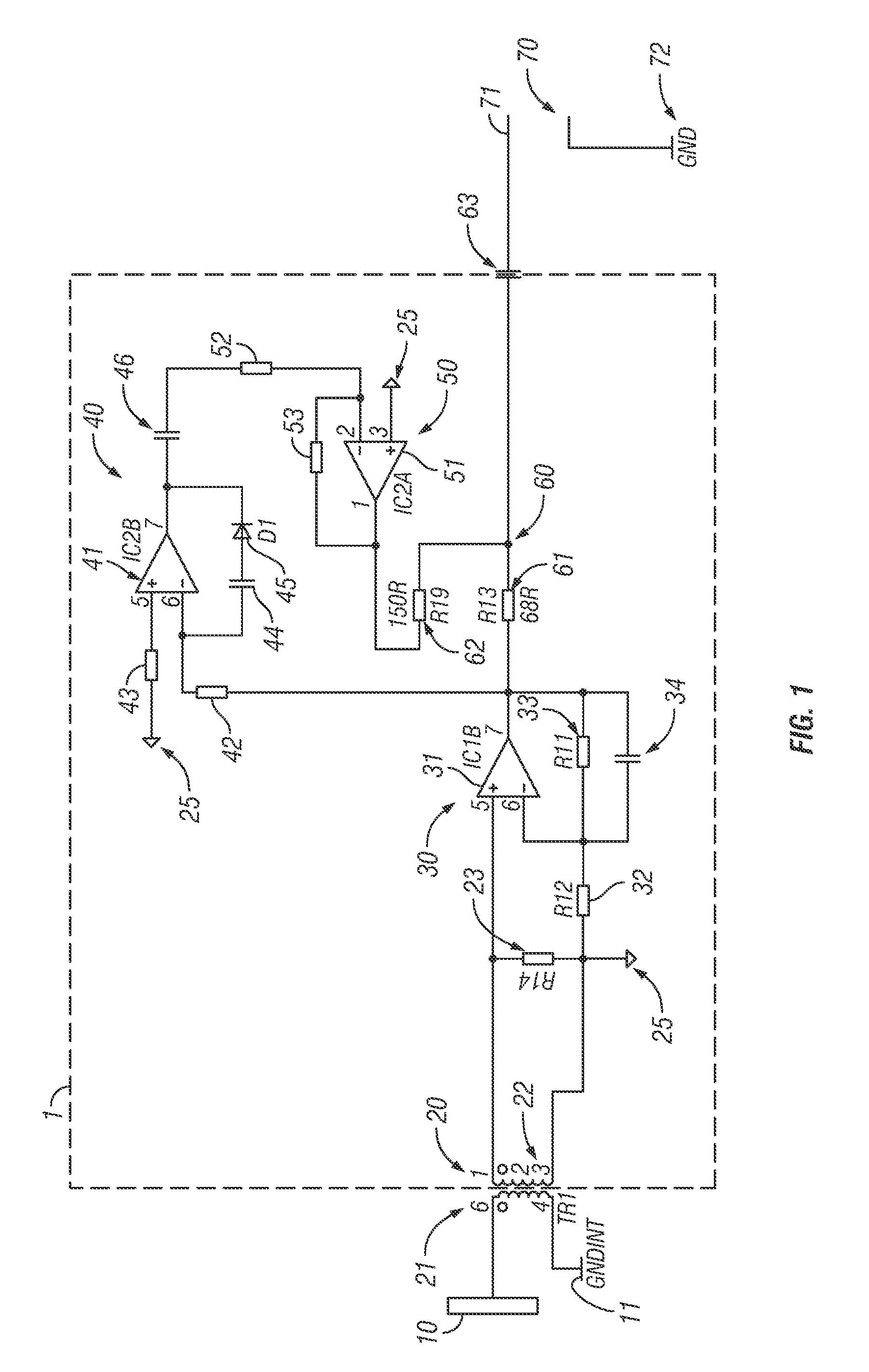
[0030]Referring first to FIG. 1, there is shown a circuit diagram of a preamplifier 1 in accordance with the present invention. The preamplifier receives a detection signal from a detection electrode 10. The detection electrode is referenced to a ground 11. The detection signal is provided as an input to the preamplifier 1 through a transformer 20. The preamplifier 1 comprises: a main amplification stage 30; an integrator stage 40; an inverting amplifier 50; and an output stage 60. An output port 70 is also provided.

[0031]The detection electrode 10 is a plate in a vacuum, where a cloud of electrons is absorbed. In view of the inherent negative charge, a negative pulse of finite duration is formed. This signal is applied across the primary winding 21 of the transformer 20. A secondary winding 22 is inductively coupled to the primary winding 21 in the transformer 20 and the non-DC component of the detection signal applied across the primary winding 21 causes a voltage to form across a...


PUM


Abstract

A preamplifier is provided for correction of overshoot or undershoot effects present in a signal received from a charged particle detection electrode. The preamplifier is ground-isolated from the charged particle detection electrode and comprises: a main amplification stage, configured to receive and amplify the isolated signal; a feed-forward stage, configured to generate a compensation signal from the amplified ground-isolated signal, the compensation signal being generated to mirror the overshoot or undershoot effects; and an output, arranged to provide an output signal that is a combination of the amplified ground-isolated signal and the compensation signal. A charged particle detection arrangement comprising the preamplifier is also provided.

Description

FIELD OF THE INVENTION[0001]The invention relates generally to a preamplifier for a charged particle (especially ion) detection arrangement, and more particularly to a preamplifier adapted for correction of either overshoot or undershoot effects present in a signal received from a charged particle detection electrode.BACKGROUND TO THE INVENTION[0002]A detector of charged particles, such as a photomultiplier (PM) or a secondary electron multiplier (SEM) is typically used in instruments such as a mass spectrometer. These detectors offer ground-referenced electrical pulse signals (which are termed “events”), which may float on a high voltage reference (as high as 2 kV) and are normally of negative polarity due to the charge of electrons. In a mass spectrometer, such detection signals can then be used to create a mass spectrum (indicating the relative abundance of ions of different masses), for example by counting the number of events received within a discrete period of time. Improving...

Claims


Application Information

Patent Timeline
Patent Type & Authority Patents(United States)
IPC IPC(8): G01T1/00G01T1/17H04N5/32H01J49/02H03F3/45
CPCH03F3/45475G01T1/17H04N5/32H01J49/02H01J49/022H01J49/025H03F2200/261H03F2200/534H03F2203/45512H03F2203/45518H03F2203/45528H03F2203/45594H03F2203/45621H01J49/0022
Inventor HEMING, RICHARD
Owner THERMO FISHER SCI BREMEN
Why Eureka
Try Eureka