
Ultrasonic diagnosis apparatus, image processing apparatus, control method for ultrasonic diagnosis apparatus, and image processing method

a technology of ultrasonic diagnosis and ultrasonic wave, applied in the field of ultrasonic diagnosis apparatus, image processing apparatus, control method of ultrasonic diagnosis apparatus, image processing method, etc., can solve the problems of affecting the accuracy of ultrasonic images, and limiting the application of this technique in the first reference, so as to improve the reduction accuracy of speckle and noise and increase the reduction processing speed

Active Publication Date: 2015-08-25
TOSHIBA MEDICAL SYST CORP
View PDF8 Cites 5 Cited by
  • Summary
  • Abstract
  • Description
  • Claims
  • Application Information

AI Technical Summary

Benefits of technology

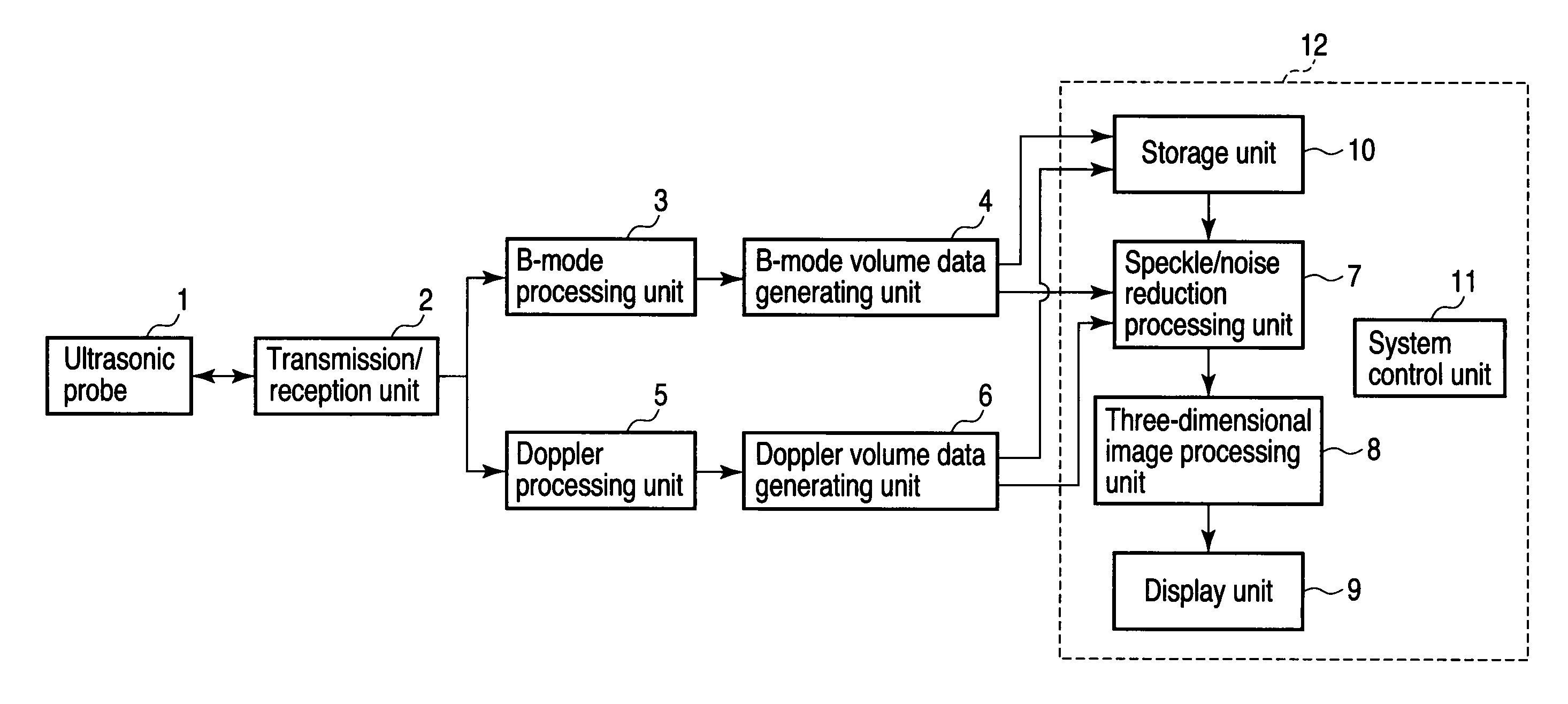
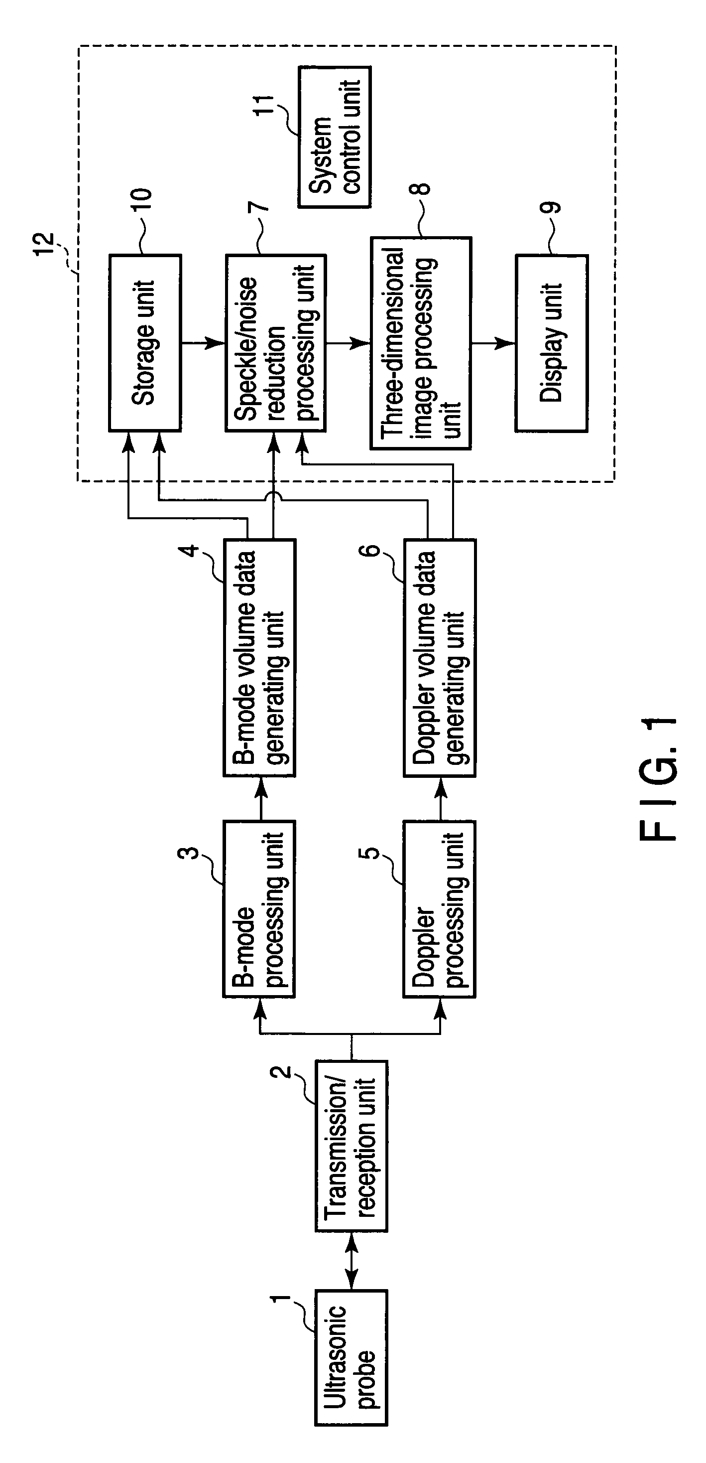
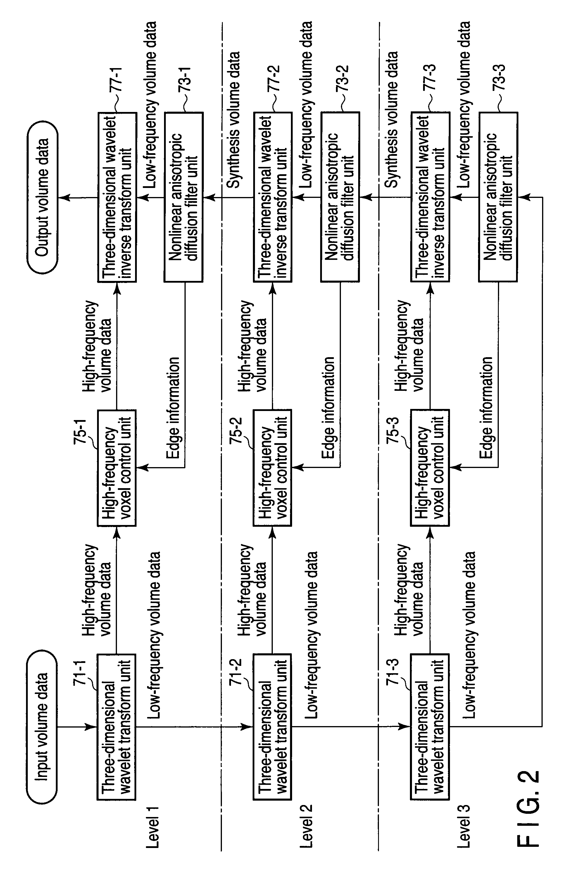
The present invention provides an ultrasonic diagnosis apparatus and image processing method that can improve the reduction accuracy of speckle and noise in volume data and increase the reduction processing speed. The apparatus includes an ultrasonic probe, transmission / reception unit, and generating unit to generate first volume data based on the echo signals received from the subject. A reduction unit generates low-frequency and high-frequency volume data based on the first volume data. A filter unit applies a nonlinear anisotropic diffusion filter to the low-frequency volume data to enhance the three-dimensional structure patterns. The high-frequency voxel control unit performs edge enhancement processing on the high-frequency volume data. A second volume data generating unit generates second volume data with reduced speckle and noise based on the low-frequency volume data to which the nonlinear anisotropic diffusion filter is applied and the high-frequency volume data for which edge enhancement processing is performed. The image processing method includes generating low-frequency and high-frequency volume data, calculating three eigenvalues, applying a nonlinear anisotropic diffusion filter, performing edge enhancement processing, and generating second volume data with reduced speckle and reduced noise.

Problems solved by technology

The ultrasonic waves reflected by a plurality of nearby subject tissues interfere with each other due to their phases.
Speckle hinders the accurate observation of the position and shape of the boundary of a subject tissue.
However, the application of this technique in the first reference is limited to two-dimensional ultrasonic images.
However, the application of the second reference is also limited to two-dimensional ultrasonic images.
In this case, however, as compared with the speckle reduction accuracy on a given surface to which a two-dimensional filter is applied, the speckle reduction accuracy on two surfaces vertically intersecting the given surface is low.
The third reference, however, does not disclose any method of linking each eigenvalue of a three-dimensional structure tensor to a three-dimensional diffusion equation.

Method used


Image

  • Ultrasonic diagnosis apparatus, image processing apparatus, control method for ultrasonic diagnosis apparatus, and image processing method
  • Ultrasonic diagnosis apparatus, image processing apparatus, control method for ultrasonic diagnosis apparatus, and image processing method
  • Ultrasonic diagnosis apparatus, image processing apparatus, control method for ultrasonic diagnosis apparatus, and image processing method

Examples


first modification

(First Modification)

[0099]An ultrasonic diagnosis apparatus, an image processing apparatus 12, a control method for the ultrasonic diagnosis apparatus, and an image processing method according to the first modification of this embodiment will be described below. Note that the same reference numerals as in this embodiment denote constituent elements having almost the same functions and arrangements, and a repetitive description will be made only when required.

[0100]The ultrasonic diagnosis apparatus according to the first modification executes speckle / noise reduction processing after performing three-dimensional image processing for volume data. FIG. 9 is a block diagram showing the arrangement of the ultrasonic diagnosis apparatus according to the first modification. The B-mode volume data generating unit 4 supplies generated B-mode volume data to the three-dimensional image processing unit 8. The Doppler volume data generating unit 6 supplies generated Doppler volume data to the th...

second modification

(Second Modification)

[0105]The image processing apparatus 12 according to the above embodiment is incorporated in the ultrasonic diagnosis apparatus. However, this embodiment need not be limited to this. For example, the image processing apparatus 12 may be incorporated in an X-ray computed tomography apparatus, magnetic resonance imaging apparatus, or nuclear medicine diagnosis apparatus. In addition, the image processing apparatus 12 may be a workstation connected to an image diagnosis apparatus such as an ultrasonic diagnosis apparatus, X-ray computed diagnosis apparatus, magnetic resonance imaging apparatus, or nuclear medicine diagnosis apparatus via a network. That is, volume data to be processed according to this embodiment does not depend on the type of image diagnosis apparatus. The image processing apparatus 12 according to the second modification can execute the above speckle / noise reduction processing for the volume data generated by any type of image diagnosis apparatus...


PUM


Abstract

A transmission / reception unit transmits an ultrasonic wave to a subject via the ultrasonic probe, receives an ultrasonic wave reflected by the subject, and outputs an echo signal corresponding to the received ultrasonic wave. A first volume data generating unit generates first volume data based on the echo signal. A second volume data generating unit generates second volume data by applying, to each voxel contained in the first volume data, three-dimensional filtering with a filtering characteristic corresponding to three-dimensional directivity of the voxel. An image data generating unit generates data of a two-dimensional ultrasonic image based on the second volume data.

Description

CROSS-REFERENCE TO RELATED APPLICATIONS[0001]This application is based upon and claims the benefit of priority from prior Japanese Patent Application No. 2009-051145, filed Mar. 4, 2009, the entire contents of which are incorporated herein by reference.BACKGROUND OF THE INVENTION[0002]1. Field of the Invention[0003]The present invention relates to an ultrasonic diagnosis apparatus, an image processing apparatus, a control method for the ultrasonic diagnosis apparatus, and an image processing method which reduce speckle and noise contained in volume data.[0004]2. Description of the Related Art[0005]An ultrasonic diagnosis apparatus applies the ultrasonic pulses generated from the transducers incorporated in an ultrasonic probe into a subject, and receives the ultrasonic waves reflected by the subject through the transducers. The ultrasonic diagnosis apparatus then generates an echo signal corresponding to the received ultrasonic waves, generates ultrasonic image data based on the gen...

Claims


Application Information

Patent Timeline
Patent Type & Authority Patents(United States)
IPC IPC(8): A61B8/14A61B8/00A61B8/08G06T5/00G06T5/10G01S7/52
CPCA61B8/14A61B8/4483A61B8/483G06T5/002G06T5/003G06T5/10G01S7/52077G06T2207/10136G06T2207/20016G06T2207/20064G06T2207/20192G06T5/73G06T5/70
Inventor OSUMI, RYOTA
Owner TOSHIBA MEDICAL SYST CORP
Learn More