Center hole machining method for shaft blank and center hole machining apparatus
a center hole machining and shaft blank technology, applied in the direction of total factory control, programme control, electric programme control, etc., can solve the problems of not addressing at all the reduction of the machining allowance of the shaft blank for reducing material cost, the shaft blank cannot be finished in a shape that meets design values, and the entire thickness of the shaft blank, etc., to achieve the effect of reducing the material cos
- Summary
- Abstract
- Description
- Claims
- Application Information
AI Technical Summary
Benefits of technology
Problems solved by technology
Method used
Image
Examples
first exemplary embodiment
1. First Exemplary Embodiment
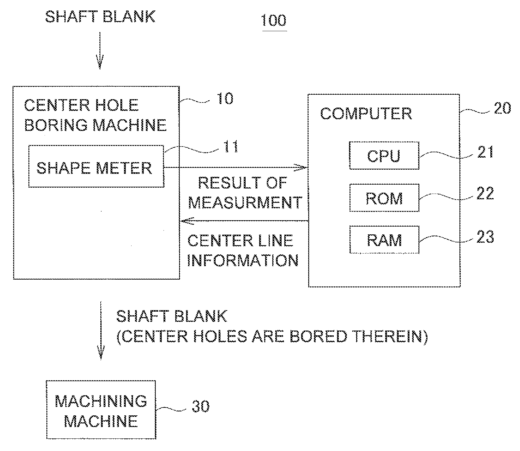
[0053]FIG. 4 illustrates a shaft machining system including a center hole machining machine 10 according to an exemplary embodiment of the present invention. The shaft machining system 100 includes the center hole machining machine 10, a computer 20 and a machining machine 30. The center hole machining machine 10 is configured to bore a center hole in each of the both end surfaces of a shaft blank. The computer 20 is configured to execute a processing for determining the position of a center hole to be bored in each of the both end surfaces of the shaft blank. The machining machine 30 is configured to execute a predetermined working for the shaft blank after the center holes are bored in the shaft blank.
[0054]The center hole machining machine 10 includes a shape meter 11, which is an example of a shape data obtaining unit configured to measure the shape of a shaft blank.
[0055]The shape meter 11 includes, for instance, either a ...
example
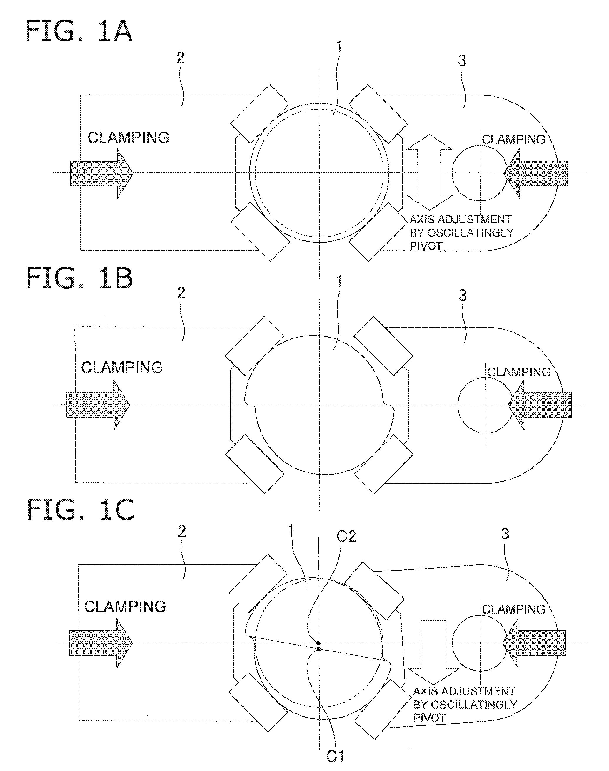
[0085]Shifting of a center axis will be specifically explained with reference to FIGS. 9A and 9B. It should be noted that FIG. 9A illustrates a case that machining allowance is insufficient in one position whereas FIG. 9B illustrates a case that machining allowance is insufficient in a plurality of positions.
[0086]As illustrated in a diagram (a) of FIG. 9A, when machining allowance is either “zero” or “minus” in one position (FIG. 9 exemplifies a case of “minus” machining allowance), the center axis is shifted on a straight line connecting the center axis and the prospective machining portion towards the opposite side of the position where machining allowance is insufficient, so that the same amount of machining allowance can be produced on the both radial sides as illustrated in a diagram (b) of FIG. 9A. When machining allowance becomes insufficient in another position after the shifting of the center axis as illustrated in a diagram (c) of FIG. 9A, the aforementioned processing is...
second exemplary embodiment
2. Second Exemplary Embodiment
[0089]The aforementioned exemplary embodiment has exemplified the case that the shaft blank is formed in a cylindrical shape. However, the present invention can be similarly applied to such a case that a cam shaft 40 is machined as illustrated in FIG. 10. In this case, the cam shaft 40 includes cylindrical journal portions 41a to 41e and cam portions 42a to 42d. Similarly to the aforementioned exemplary embodiment, the least-square method for a true circle is herein applied to the journal portions 41a to 41e. On the other hand, best-fitting based on the least-square method is applied to the design values of the cam shapes of the cam portions 42a to 42d. Further, as to the cam shapes, relative angles are preliminarily set among the respective cam portions. Therefore, a center axis is calculated by incorporating the relative angles into best-fit calculation.
PUM
 Abstract
Description
Claims
Application Information
 - R&D
- Intellectual Property
- Life Sciences
- Materials
- Tech Scout
- Unparalleled Data Quality
- Higher Quality Content
- 60% Fewer Hallucinations
Browse by: Latest US Patents, China's latest patents, Technical Efficacy Thesaurus, Application Domain, Technology Topic, Popular Technical Reports.
© 2025 PatSnap. All rights reserved.Legal|Privacy policy|Modern Slavery Act Transparency Statement|Sitemap|About US| Contact US: help@patsnap.com


