
Vacuum pumping system

a vacuum pumping and vacuum technology, applied in the direction of machines/engines, mechanical equipment, positive displacement liquid engines, etc., can solve the problems of pump failure, loss of pumping performance, solid material accumulation and accumulation of powders,

Active Publication Date: 2015-09-15
EDWARDS LTD
View PDF12 Cites 1 Cited by
  • Summary
  • Abstract
  • Description
  • Claims
  • Application Information

AI Technical Summary

Benefits of technology

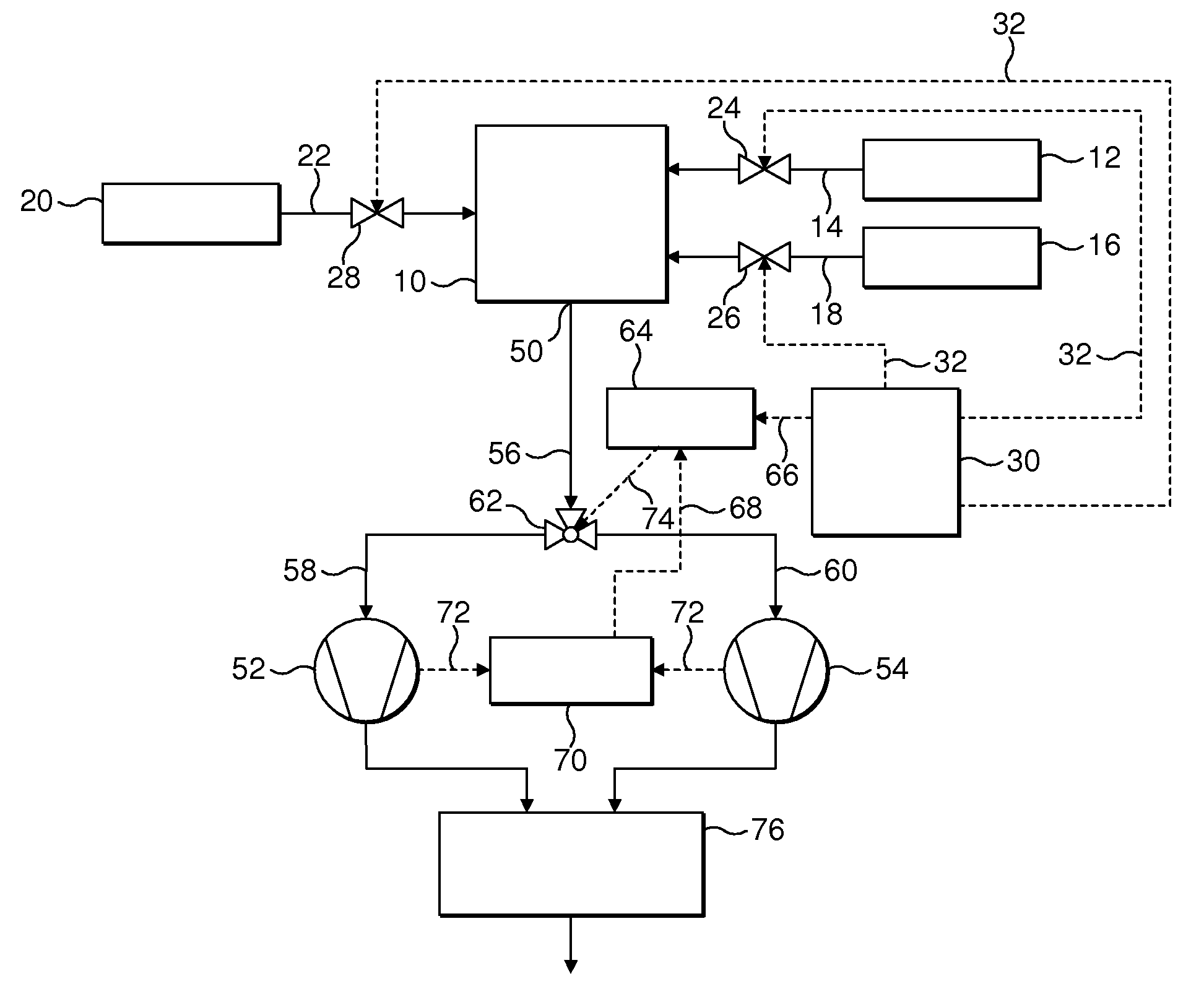
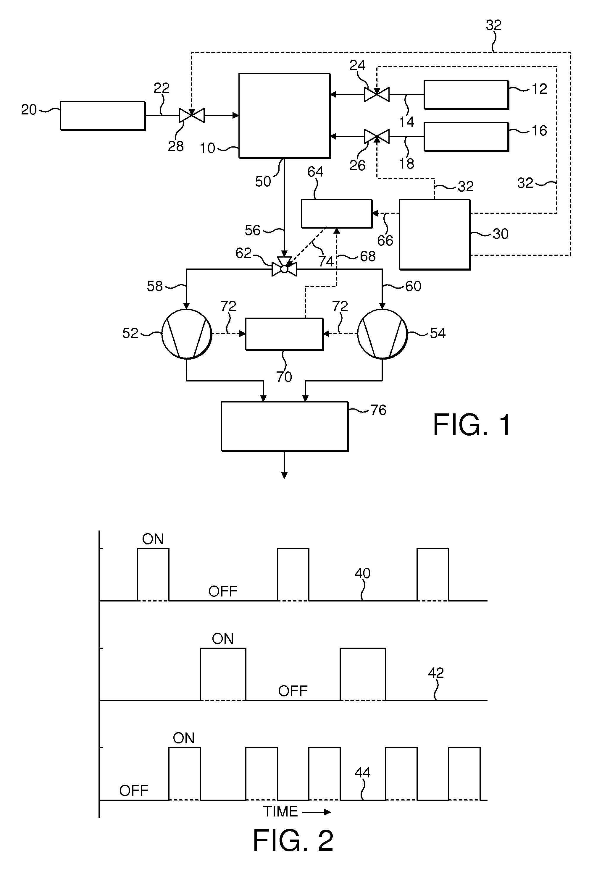
The present invention relates to a vacuum pumping system for evacuating a chamber. The system includes two vacuum pumps, two exhaust paths, and valve means for selectively opening and closing the exhaust paths. The system is designed to selectively convey a first or second reactant-rich gas exhaust from the chamber depending on the condition of the vacuum pumps. The technical effect of the invention is to provide a more efficient and flexible vacuum pumping system for evacuating chambers.

Problems solved by technology

In the event that the non-reacted precursors meet within the vacuum pumping system, cross-reaction of the precursors can occur, and this can result in both the deposition of solid material and the accumulation of powders within the foreline and the vacuum pump.
Particulates and powders that have accumulated within the pump can effectively fill the vacant running clearance between the rotor and stator elements of the pump, leading to a loss of pumping performance and ultimately pump failure.
Periodic pump cleaning or replacement is then required to maintain pumping performance, resulting in costly process downtime and increasing manufacturing costs.
This reduces the extent of the mixing of the non-reacted precursors within the exhaust lines and the vacuum pumps, increasing process uptime and throughput.
A problem associated with both the conventional vacuum pumping system and the vacuum pumping system described in US 2004 / 0107897 is that if the, or one of the, vacuum pumps fails during processing within the process chamber, the batch of substrates currently being processed within the chamber will be lost.
In order to increase product throughput, the numbers of substrates being processed within a process chamber at any one time may be anywhere between 25 and 100 or more, and so failure of a vacuum pump during a deposition process may be very costly.

Method used


Image

  • Vacuum pumping system
  • Vacuum pumping system
  • Vacuum pumping system

Examples


Embodiment Construction

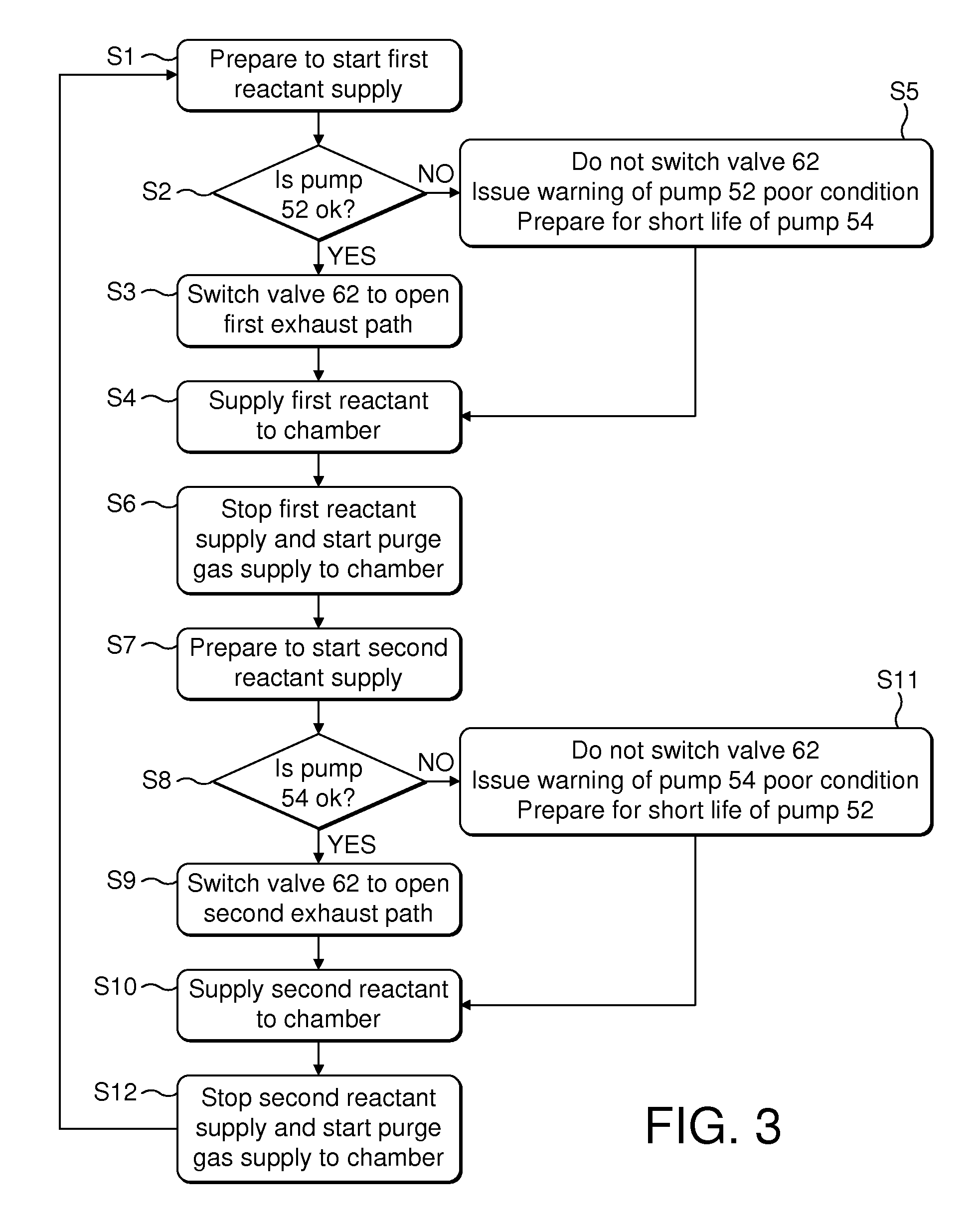
[0017]The present invention provides a vacuum pumping system for evacuating a chamber, the system comprising a first vacuum pump, a second vacuum pump, a first exhaust path along which gas is conveyed from the chamber to the first vacuum pump, a second exhaust path along which gas is conveyed from the chamber to the second vacuum pump, means for monitoring a condition of each vacuum pump, valve means for selectively opening and closing the first and second exhaust paths, and means for controlling the valve means to, depending on the condition of the vacuum pumps, either(i) alternately convey a first reactant-rich gas exhaust from the chamber along the first exhaust path, and a second reactant-rich gas exhaust from the chamber along the second exhaust path, or (ii) convey both the first reactant-rich gas and the second reactant-rich gas along a common exhaust path.

[0018]In accordance with the invention, the condition of the vacuum pumps is monitored during use. When both vacuum pumps...


PUM

PropertyMeasurementUnit
Temperatureaaaaaaaaaa

Abstract

A vacuum pumping system comprises a primary foreline for receiving a gas stream from an outlet of a chamber, a first vacuum pump for evacuating the chamber, a second vacuum pump for evacuating the chamber, a first secondary foreline for conveying gas from the primary foreline to the first vacuum pump, a second secondary foreline for conveying gas from the primary foreline to the second vacuum pump, and valve means for selectively connecting a chosen one of the first and second secondary forelines to the primary foreline. The condition of the vacuum pumps is monitored during use. When both vacuum pumps are operating normally, the valve means is controlled to divert a first reactant-rich gas from the primary foreline into the first secondary foreline, and to divert a second reactant-rich gas from the primary foreline to the second secondary foreline, thereby inhibiting mixing of the first and second reactants within the vacuum pumps. However, in the event that the condition of one of the vacuum pumps indicates that one of the pumps is likely to fail during a current process within the chamber, the valve means is controlled to divert both the first reactant-rich gas and the second reactant-rich gas to the other vacuum pump, thereby preventing the potentially costly loss of a batch of substrates within the chamber.

Description

FIELD OF THE INVENTION[0001]The present invention relates to a vacuum pumping system, and finds particular use in an apparatus used to draw gases from a process chamber in which a pulsed gas delivery system is used to supply gases to the process chamber.BACKGROUND OF THE INVENTION[0002]Pulsed gas delivery systems are commonly used in the formation of multi-layer thin films on a batch of substrates located in a process chamber. One such technique for forming thin films on substrates is atomic layer deposition (ALD), in which gaseous reactants, or “precursors”, are sequentially delivered to a process chamber to form very thin layers, usually on an atomic-layer scale, of materials on the substrates.[0003]By way of example, a high dielectric constant capacitor may be formed on a silicon wafer using an ALD technique through the sequential deposition of hafnium oxide (HfO2) and aluminium oxide (Al2O3) thin films. HfO2 thin films may be formed by the sequential supply of a hafnium precurso...

Claims


Application Information

Patent Timeline
IPC IPC(8): C23C16/455C23C16/54B05C11/00F04B41/06C23C16/44
CPCF04B41/06C23C16/4412C23C16/45525C23C16/45544C23C16/44C23C16/56F04B41/00
Inventor BAILEY, CHRISTOPHER MARK
Owner EDWARDS LTD
Learn More