Optical fiber for Coherent Anti-Stokes Raman scattering endoscopes

a technology of optical fiber and anti-stokes raman, applied in the field of optical fiber, can solve the problems of contaminating background signals, difficult to interrogate materials and media with conventional means, and known limitation of car endoscopy, and achieve the effect of limiting bending losses

Active Publication Date: 2015-09-29
INSTITUT NATIONAL D'OPTIQUE
View PDF9 Cites 5 Cited by
  • Summary
  • Abstract
  • Description
  • Claims
  • Application Information

AI Technical Summary

Benefits of technology

[0010]In accordance with still another aspect, there is provided an optical fiber for use in a Coherent Anti-Stokes Raman Scattering (CARS) endoscope. The optical fiber comprising: a core having a radius a1 and a refractive index n1, the core extending along a longitudinal axis, the core being adapted to guide a Stokes lightwave at a Stokes wavelength and a pump lightwave at a pump wavelength along a first propagation direction parallel to the longitudinal axis, said core being single-mode at the Stokes and pump wavelengths, each of the Stokes lightwave and the pump lightwave having a direction of polarization; an inner cladding layer surrounding the core, the inner cladding layer having a refractive index n2, the refractive index n1 being higher than the refractive index n2, the refractive index n1 and the refractive index n2 being chosen to obtain a predetermined value of the numerical aperture of the core; a trench cladding layer surrounding the inner cladding layer and having a trench inner radius a2, a width W, and a refractive index n3, the refractive index n3 being lower than the refractive index n2; an intermediate cladding layer surrounding the trench cladding layer and having a refractive index n4, the refractive index n4 being higher than the refractive index n3 by a depth δn2 equal to a difference n4−n3; two stress-applying parts enclosed within the intermediate cladding layer and disposed symmetrically on either side of the longitudinal axis, each stress-applying part being disposed substantially parallel to the longitudinal axis, the stress-applying parts being adapted to maintain the direction of polarization of the pump lightwave and of the Stokes lightwave; and an outer cladding layer surrounding the intermediate cladding layer and having a refractive index n5, the refractive index n5 being lower than the refractive index n4 allowing said optical fiber to act as a multimode waveguide for guiding a CARS lightwave at a CARS wavelength along a second propagation direction parallel to the longitudinal axis and opposite to the first propagation direction.
[0011]In one embodiment, the width W and depth δn2 are selected to limit bending losses of a fundamental LP01 mode of the optical fiber at the Stokes wavelength below 0.5 dB / turn for a fiber curved with a radius of about 2 cm while maintaining confinement losses above 5 dB / m for a higher-order LP11 mode of the optical fiber at the pump wavelength.

Problems solved by technology

Optical probes with small footprints are employed in applications where interrogating materials and media with conventional means become difficult because of restricted access and / or environmental hazards.
A well-known limitation of CARS endoscopy comes from the generation of a contaminating background signal at the same wavelength as that of the CARS signal.
In the case of an imaging application, this contaminating background light limits the contrast of the images.
Various approaches have been proposed to mitigate this contaminating signal but, depending on the intended size of the overall probe, these approaches may not necessarily be practical.
The miniaturization of the probe may then become a challenge.
However, the double-core design has its own limitations: the injection of the pump and Stokes lightwaves into separate cores gets more complex and the lens design at the output end of the fiber must ensure good spatial overlap of the light beams on the tissue under examination, thus resulting in additional constraints to account for in the course of the design phase.
The bending losses of the fundamental LP01 mode of the fiber at the Stokes wavelength are limited while maintaining high confinement losses for the higher-order LP11 mode of the fiber at the pump wavelength.

Method used


Image

  • Optical fiber for Coherent Anti-Stokes Raman scattering endoscopes
  • Optical fiber for Coherent Anti-Stokes Raman scattering endoscopes
  • Optical fiber for Coherent Anti-Stokes Raman scattering endoscopes

Examples


first embodiment

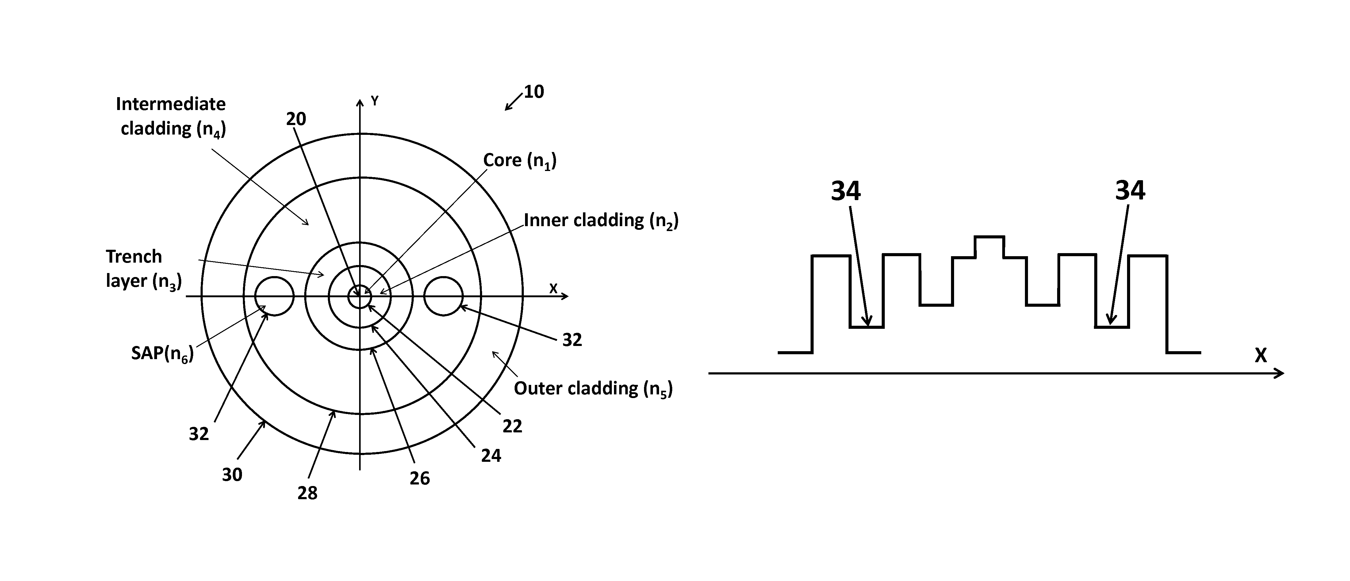
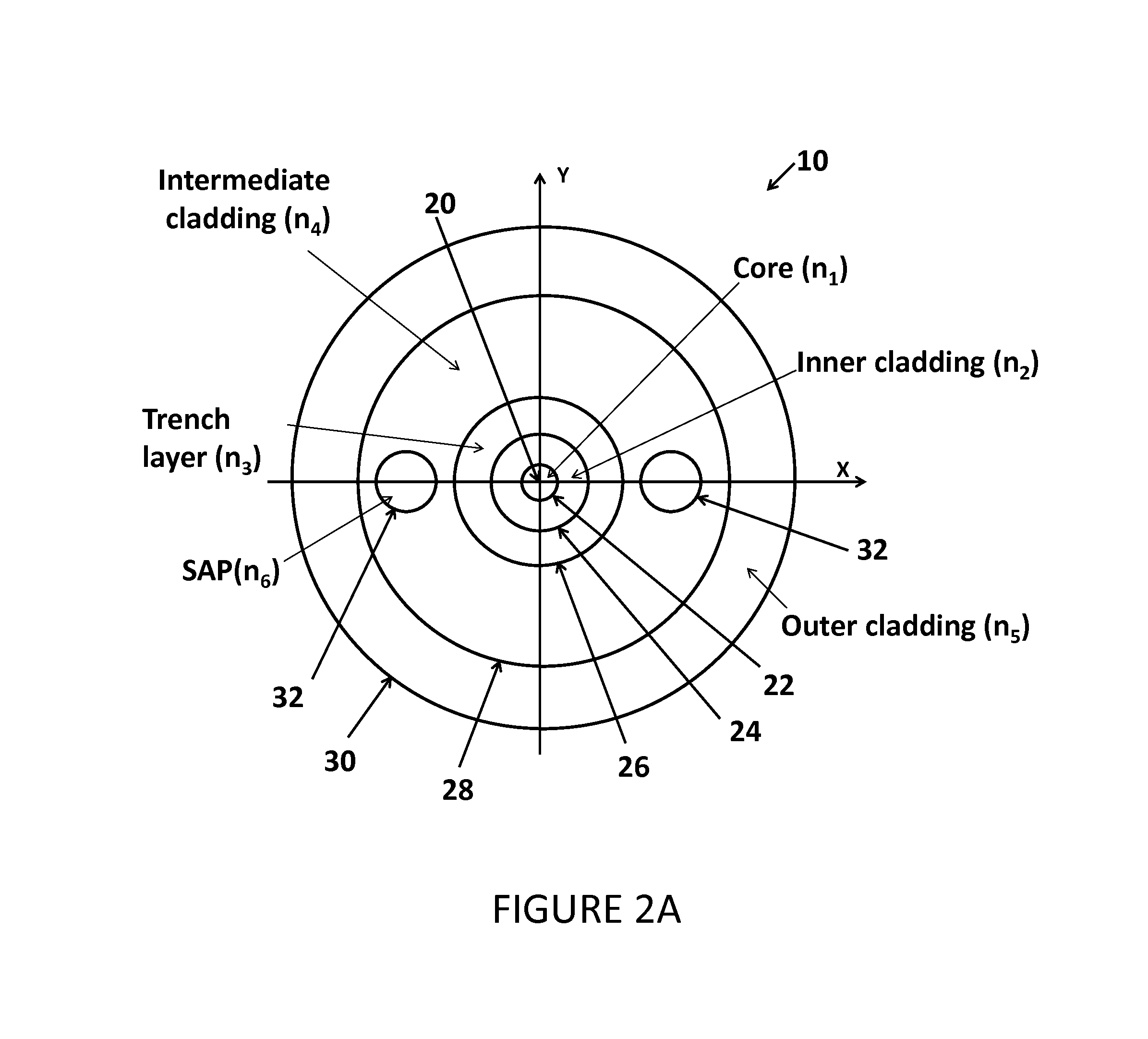
[0038]The schematic illustration of FIG. 2A depicts the structural characteristics of an optical fiber 10 that fulfills the various requirements mentioned earlier and intended for use in a CARS endoscope. Starting from the center position of the illustration, the optical fiber 10 first includes a core 22 that is single-mode for lightwaves at a pump wavelength and at a Stokes wavelength, the core 22 having a radius a1 (not shown in FIG. 2A). The core 22 is made out of an optical material having a refractive index n1 within a spectral region encompassing the wavelengths of interest. The core 22 is substantially centered on the longitudinal axis 20 of the fiber, which extends perpendicularly to the plane of FIG. 2A while being coincident with the intersection of the two orthogonal transverse axes labeled X and Y in FIG. 2A. The core 22 is surrounded by an inner cladding layer 24 having a refractive index n2, this layer being in turn surrounded by a trench cladding layer 26 having an in...

second embodiment

[0053]FIG. 5 illustrates an exemplary refractive-index profile of the optical fiber 10 in which the refractive index n4 of the intermediate cladding layer 28 differs from that of the inner cladding layer n2 by an amount Δ. This adds a degree of freedom in the optimization of the fiber design.

[0054]An optical fiber 10 having a radial refractive-index profile of the type corresponding to the first embodiment has been fabricated. The refractive-index profiles measured along two orthogonal axes X and Y transverse to the longitudinal center axis 20 of the fiber 10 are shown in FIG. 6. As it was the case in the schematic illustration of FIG. 2A, the X axis is parallel to the line that joins both SAPs 32 present in the fiber. Note that the refractive-index changes due to the presence of both SAPs 32 are not visible in FIG. 6A since the SAPs 32 are located beyond the limits of the horizontal axis of the graph.

[0055]Those skilled in the art of optical fiber design will recognize that the rad...


PUM


Abstract

An optical fiber for use in a Coherent Anti-Stokes Raman Scattering (CARS) endoscope, comprising a core guiding lightwaves at a pump wavelength and at a Stokes wavelength, the core being single-mode at both wavelengths. The core is surrounded by cladding layers, including an inner cladding layer, a trench cladding layer, an intermediate cladding layer and an outer cladding layer. The refractive index of the trench cladding layer is lower than those of both neighboring cladding layers so as to define a trench in the radial refractive-index profile. The bending losses of the fundamental LP01 mode of the fiber at the Stokes wavelength are limited while maintaining high confinement losses for the higher-order LP11 mode of the fiber at the pump wavelength. The combination of the intermediate and outer cladding layers forms a multimode waveguide for guiding a collected CARS signal generated by an object or medium probed with the endoscope.

Description

TECHNICAL FIELD[0001]The invention relates to an optical fiber and, more particularly, to an optical fiber suitable for use in a Coherent Anti-Stokes Raman Scattering (CARS) endoscope.BACKGROUND OF THE ART[0002]Optical probes with small footprints are employed in applications where interrogating materials and media with conventional means become difficult because of restricted access and / or environmental hazards. For example, such optical probes can be utilized for probing oil fields (see Nakstad et al., “Probing oil fields”, Industry Perspectives, Oil and Gas Applications, Technology Focus: Optical-fibre sensors, Nature Photonics Vol. 2, No. 3, pp. 147-149, (2008)), nuclear reactors (see PCT Pat. Appl. Pub. No. WO / 2012060563 OPTICAL FIBER PROBE FOR MEASURING PH IN NUCLEAR REACTOR COOLING SYSTEM AND PH MEASURING SYSTEM USING SAME) or contaminated soils (see Ghandehari et al., “Near-Infrared Spectroscopy for In Situ Monitoring of Geoenvironment”, JOURNAL OF GEOTECHNICAL AND GEOENVIRO...

Claims


Application Information

Patent Timeline
Patent Type & Authority Patents(United States)
IPC IPC(8): G02B6/24G02B6/024G02B6/02G02B6/036
CPCG02B6/024G02B6/02047G02B6/03661G02B6/03672G02B6/02009G02B6/0365G01N2021/653H01S3/06712H01S3/06733H01S3/302
Inventor PARE, CLAUDEZHENG, HUIMINDELADURANTAYE, PASCALCORMIER, JEAN-FRANCOIS
Owner INSTITUT NATIONAL D'OPTIQUE
Why Eureka
Try Eureka