
Method and system for demodulating signals

a signal and demodulation technology, applied in the field of demodulation sensors, can solve the problems of reducing the responsivity of the sensor and the need for alternating current supply, and achieve the effect of fast demodulation and good sensitivity

Active Publication Date: 2015-10-06
MELEXIS TECH NV
View PDF15 Cites 2 Cited by
  • Summary
  • Abstract
  • Description
  • Claims
  • Application Information

AI Technical Summary

Benefits of technology

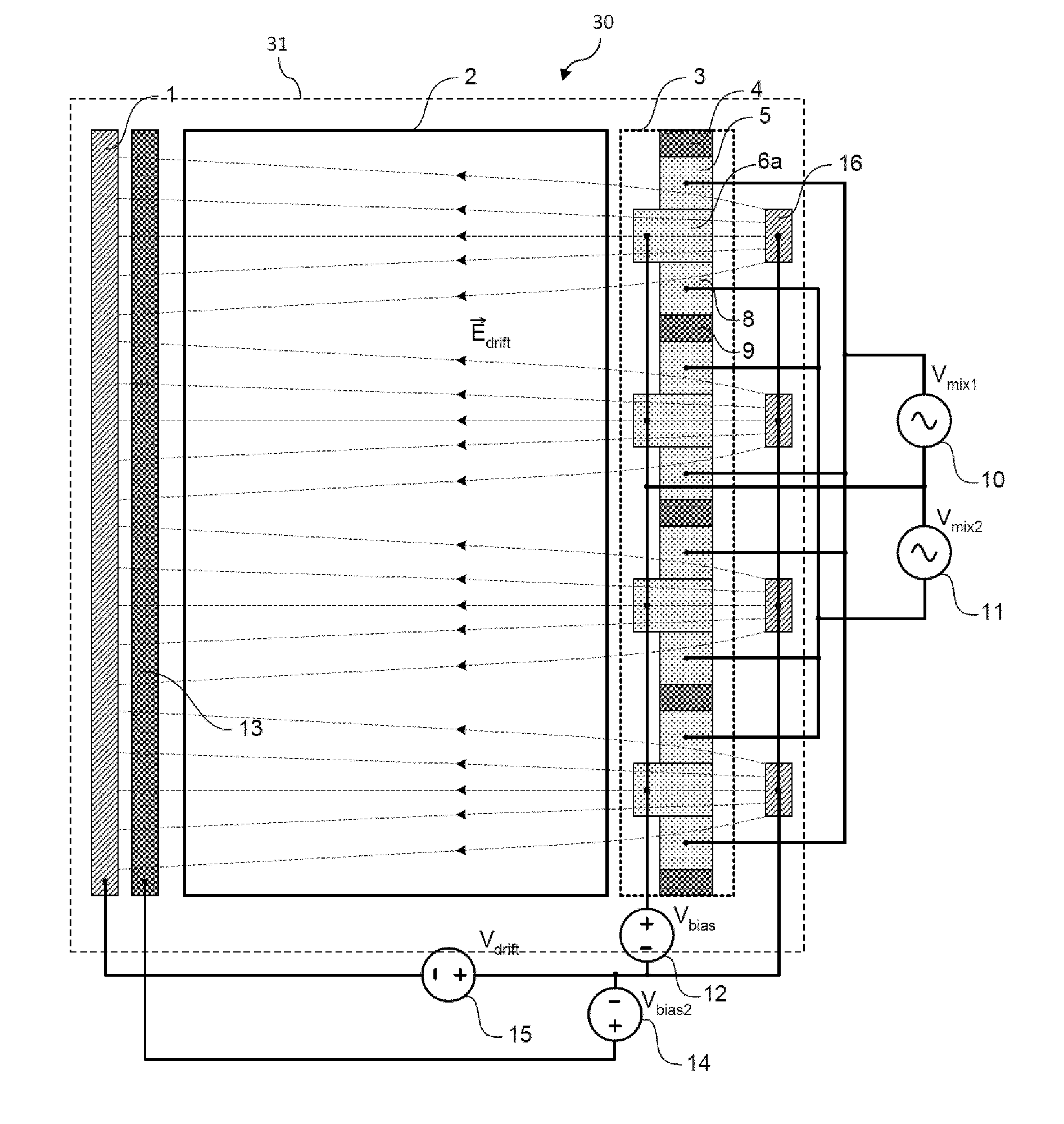
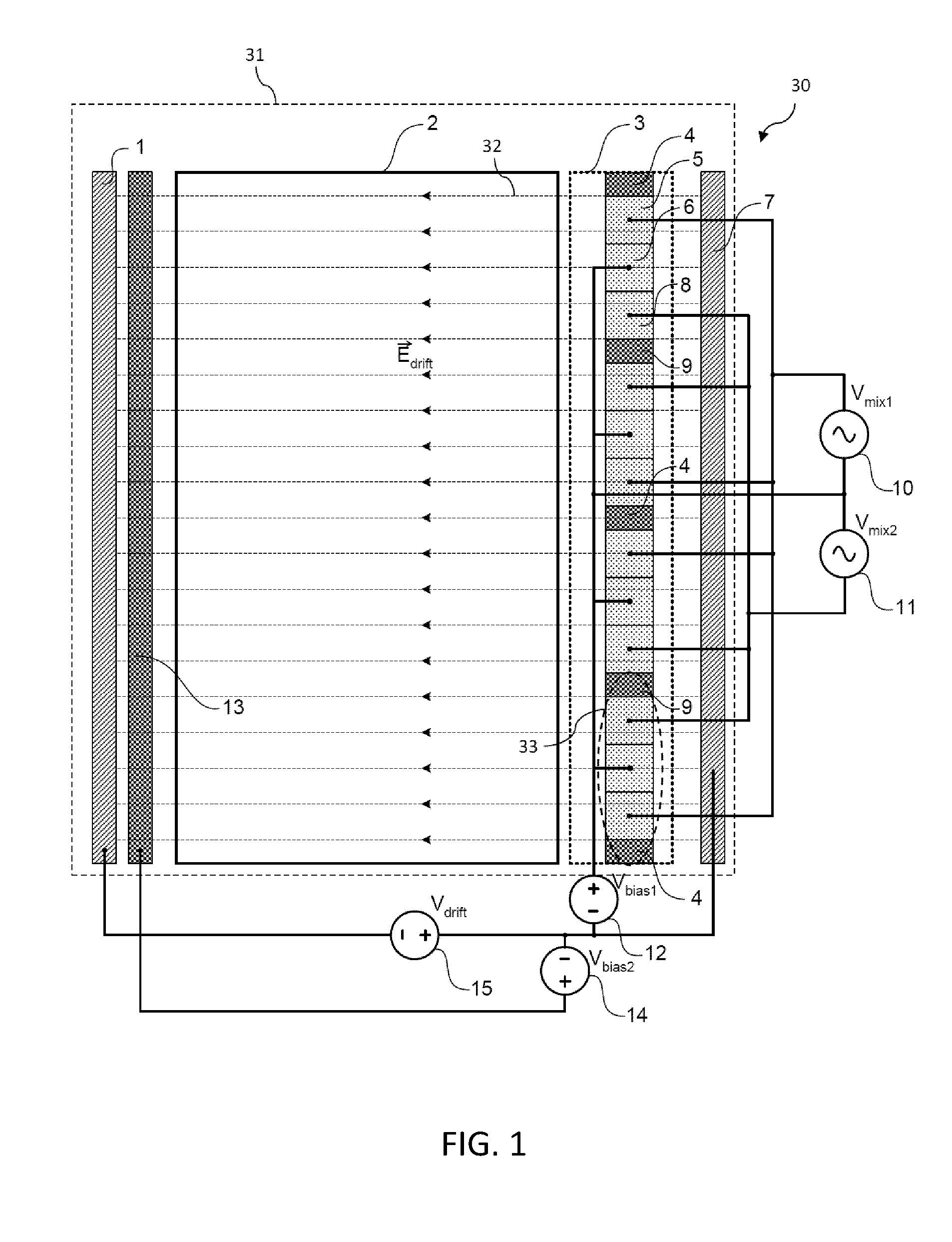
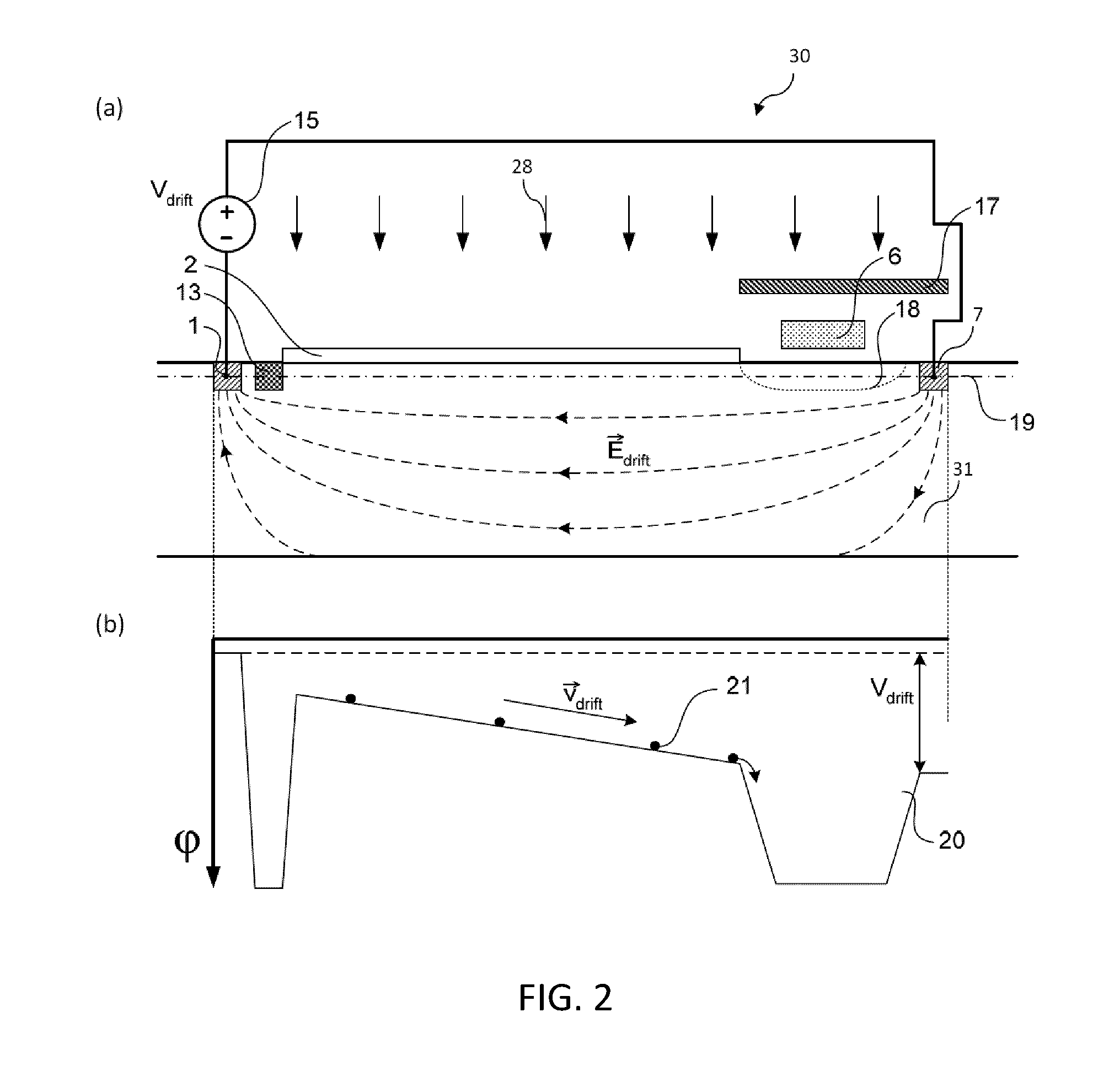
The present invention is a demodulation sensor and methods for detecting modulated signals with good sensitivity. It uses a static drift field to accelerate the generated carriers in the substrate towards the demodulation region, allowing for fast demodulation of a modulated radiation field. The sensor can be manufactured using MOS-compatible technology and can provide a CMOS-compatible sensor. It has at least one gate structure for collecting and accumulating minority carriers, which are generated in the substrate by the impinging radiation field, and means for reading out the accumulated minority carriers in that region. The sensor uses a static drift field for increased efficiency and can calculate the modulation parameters of the incident modulated radiation field. It has at least two regions for collecting and accumulation, which can be one detection region and one region acting as dump for the photoelectrons. In one embodiment, the at least one gate structure may comprise at least two gates.

Problems solved by technology

The drawbacks of this approach are the slow diffusion of the photo-generated charge carriers to the top of the sensor, the presence of the gates over the sensitive area which reduce the responsivity of the sensor and the large gate capacitance that should be driven on each toggling of the control voltage.
The drawback of this approach is the alternating current which has to be supplied to maintain an alternating electric field in the substrate.

Method used


Image

  • Method and system for demodulating signals
  • Method and system for demodulating signals
  • Method and system for demodulating signals

Examples


Embodiment Construction

[0033]The present invention will be described with respect to particular embodiments and with reference to certain drawings but the invention is not limited thereto but only by the claims. The drawings described are only schematic and are non-limiting. In the drawings, the size of some of the elements may be exaggerated and not drawn on scale for illustrative purposes. The dimensions and the relative dimensions do not correspond to actual reductions to practice of the invention.

[0034]Furthermore, the terms first, second and the like in the description and in the claims, are used for distinguishing between similar elements and not necessarily for describing a sequence, either temporally, spatially, in ranking or in any other manner. It is to be understood that the terms so used are interchangeable under appropriate circumstances and that the embodiments of the invention described herein are capable of operation in other sequences than described or illustrated herein.

[0035]Moreover, t...


PUM


Abstract

A demodulation sensor (30) is described for detecting and demodulating a modulated radiation field impinging on a substrate (31). The sensor comprises the means (1,7,15) for generating, in the substrate, a static majority current assisted drift (Edrift) field, at least one gate structure (33) for collecting and accumulating minority carriers (21), the minority carriers generated in the substrate by the impinging radiation (28) field. The at least one gate structure comprises at least two regions (4,9,18) for the collection and accumulation of the minority carriers (21) and at least one gate (5,6,8) adapted for inducing a lateral electric drift field under the gate structure, the system thus being adapted for directing the minority carriers (21) towards one of the at least two regions (4,9) under influence of the static majority current assisted drift field and the lateral electric drift field induced by the at least one gate, and a means for reading out the accumulated minority carriers in that region.

Description

FIELD OF THE INVENTION[0001]The present invention relates to the field of detection of electromagnetic radiation impinging on semiconductor material. More particularly, the present invention relates to a demodulation sensor and a method for the detection and demodulation of temporally modulated electromagnetic radiation fields for the use in time of flight applications, where the phase shift of a modulated radiation field is determined to estimate the distance to a target.BACKGROUND OF THE INVENTION[0002]The behavior of many systems in technology is investigated by means of demodulation techniques, whereby the system is excited with a modulated signal and the properties of the reflected radiation are used to determine the characteristics of the system under investigation.[0003]A particular example of measuring techniques which require the demodulation of a temporally modulated electromagnetic radiation field are the time of flight (TOF) distance measurements, based on the fact that ...

Claims


Application Information

Patent Timeline
Patent Type & Authority Patents(United States)
IPC IPC(8): G01J4/04H01L31/0224G01J9/00G01S7/491H01L27/146G01S7/4914G01S17/894
CPCG01J9/00G01S7/4914H01L31/0224H01L27/14603G01S17/894G01S3/78H01L27/146H01L27/148H01L31/09H01L31/02
Inventor SELIUCHENKO, VOLODYMYRKUIJK, MAARTEN
Owner MELEXIS TECH NV
Learn More