
Surface treatment method for atomically flattening a silicon wafer and heat treatment apparatus

a technology of surface treatment and silicon wafer, which is applied in lighting and heating apparatus, drying machines with progressive movements, furnaces, etc., can solve the problems of not being disclosed in the patent document 1 and achieve the effects of low cost, no slip line, and reduced gas us

Inactive Publication Date: 2015-10-13
TOHOKU UNIV
View PDF23 Cites 0 Cited by
  • Summary
  • Abstract
  • Description
  • Claims
  • Application Information

AI Technical Summary

Benefits of technology

The invention provides a way to make silicon wafers with very smooth surfaces, even if they are very large (500 mm in diameter or larger). The method also allows for a faster and more efficient treatment of larger wafers, using a higher-purity gas for a higher yield.

Problems solved by technology

However, no description is made at all in Patent Document 1 about whether the method is suitable for mass production, whether the method is applicable to a larger-diameter silicon wafer, whether, even if the method is applicable thereto, the yield is high enough to be suitable for mass production, or the like.
That is, Patent Document 1 does not disclose whether or not it is possible to prevent the formation of a crystal defect even if a large number of large-diameter silicon wafers are continuously and successively treated for mass production.

Method used


Image

  • Surface treatment method for atomically flattening a silicon wafer and heat treatment apparatus
  • Surface treatment method for atomically flattening a silicon wafer and heat treatment apparatus
  • Surface treatment method for atomically flattening a silicon wafer and heat treatment apparatus

Examples


example 1

[0095]First, a silicon wafer which had a diameter of 200 mmφ and which had a surface of (100) orientation was prepared and the silicon wafer surface was cleaned in the following sequence.

[0096]First, the silicon wafer surface was cleaned with O3 water for 10 minutes, cleaned with dilute HF (0.5 wt %) for 1 minute, and finally rinsed with ultrapure water for 3 minutes.

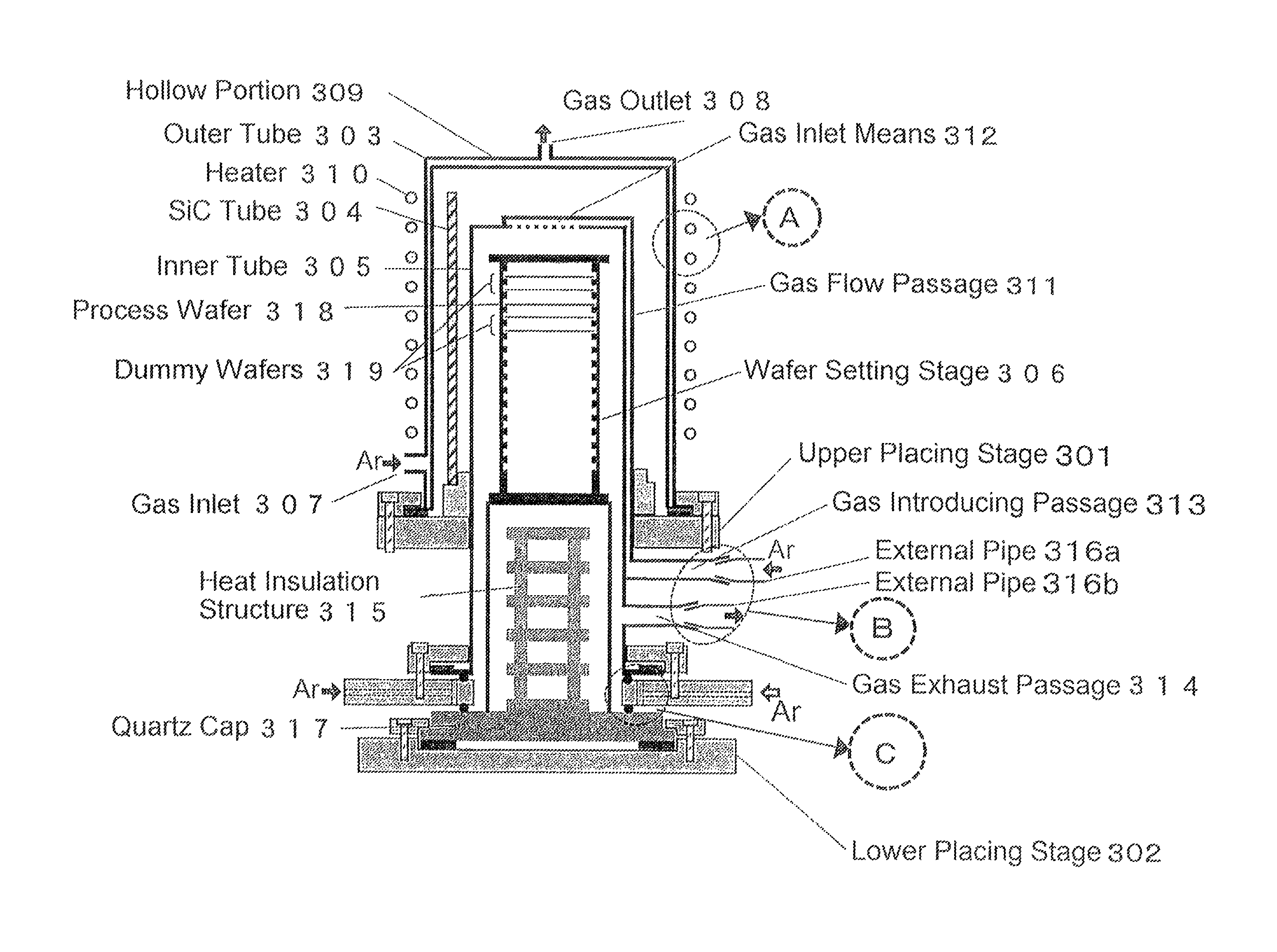
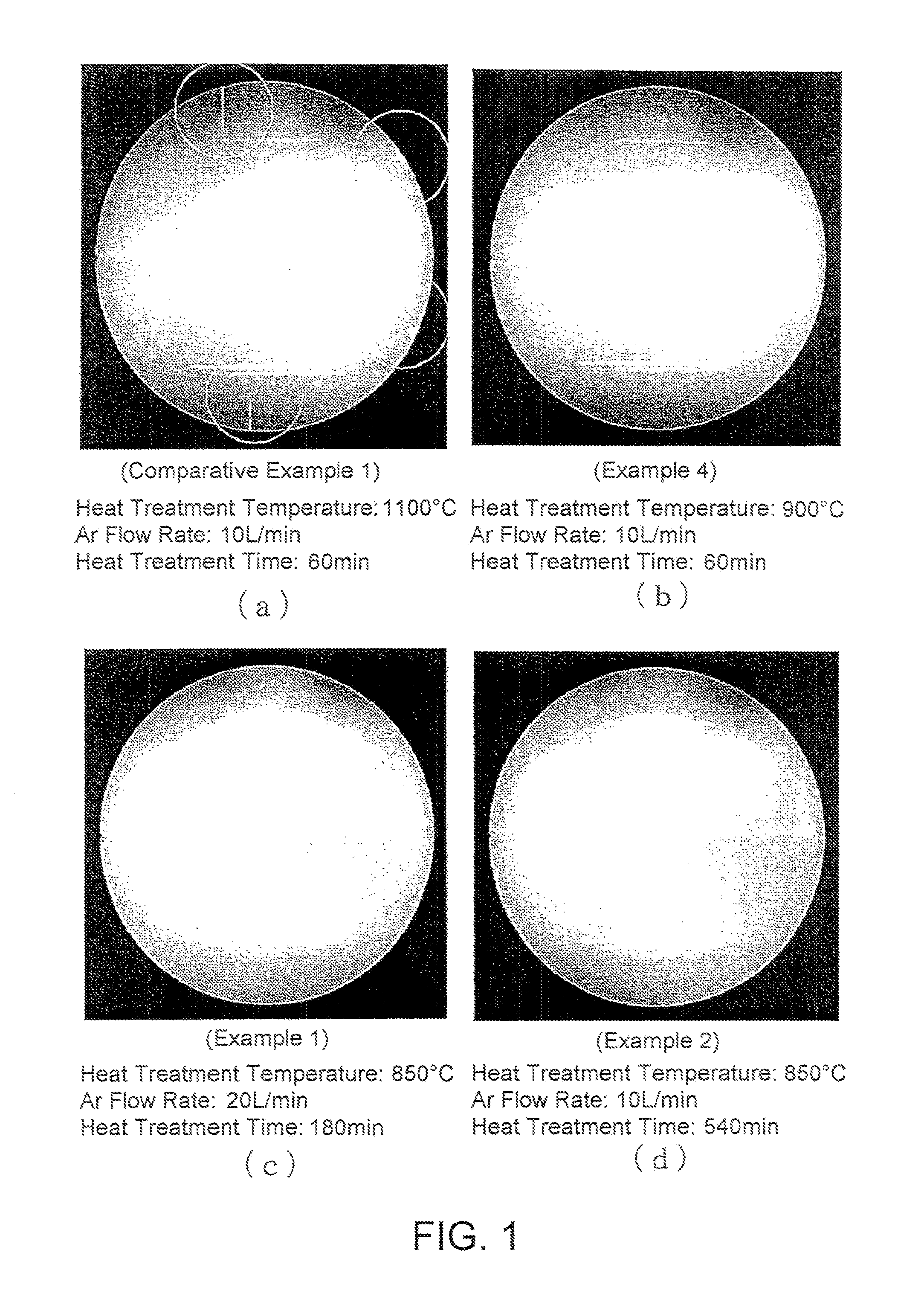
[0097]Then, the silicon wafer was placed in a heat treatment apparatus shown in FIG. 3. While Ar which included 0.2 ppb or less of moisture and 0.1 ppb or less of O2 was caused to flow at a flow rate of 20 L / min, a heat treatment was carried out under conditions of a heat treatment temperature of 850° C. and a heat treatment time of 180 minutes.

[0098]It is to be noted that the heat treatment was not carried out in the manner described above with reference to FIGS. 4, 5, and 6, but was carried out under heat treatment apparatus conditions equivalent to those of a heat treatment apparatus shown in FIG. 9 of the above-ment...

example 2

[0100]A sample was prepared under the same conditions as in Example 1 except that the Ar flow rate was set to 10 L / min and the heat treatment time (holding time) to 540 minutes.

example 3

[0101]A sample was prepared under the same conditions as in Example 1 except that the Ar flow rate was set to 10 L / min and the heat treatment time (holding time) to 270 minutes.


PUM


Abstract

In a silicon wafer which has a surface with a plurality of terraces formed stepwise by single-atomic-layer steps, respectively, no slip line is formed.

Description

[0001]This application is a continuation-in-part of International Application No. PCT / JP2011 / 052107, filed on Feb. 2, 2011, and International Application No. PCT / JP2012 / 059374, filed on Apr. 5, 2012, the disclosures of which are incorporated herein in their entirety by reference.[0002]This application is based upon and claims the benefit of priority from Japanese Patent Application No. 2010-023101, filed on Feb. 4, 2010, the disclosure of which is incorporated herein in its entirety by reference.TECHNICAL FIELD[0003]This invention relates to a method of flattening a surface of a silicon wafer for forming a semiconductor device such as an IC or LSI.BACKGROUND ART[0004]The asperity of a surface of a silicon wafer for forming a semiconductor device such as an IC or LSI is a factor which prevents an improvement of current drivability of a MOSFET (Metal Oxide Semiconductor Field Effect Transistor), as shown in, for example, Non-Patent Document 1 and, therefore, the surface is required to...

Claims


Application Information

Patent Timeline
Patent Type & Authority Patents(United States)
IPC IPC(8): H01L29/06H01L21/677H01L21/67H01L21/302H01L21/02F27B17/00H01L21/324
CPCF27B17/0025H01L21/02052H01L21/02238H01L21/02252H01L21/67757H01L21/3247H01L21/67017H01L21/67109H01L21/67126H01L21/302
Inventor OHMITERAMOTO, AKINOBUSUWA, TOMOYUKI
Owner TOHOKU UNIV
Learn More