
Method and device for preventing a surging of fluids in a tank of a tank truck

a technology for tank trucks and fluids, which is applied in the direction of tank vehicles, transportation items, instruments, etc., can solve the problems of low frequency oscillation of vehicles, unwanted sighting, and smokey engagement of brakes, so as to reduce the gear change speed of the tank truck, prevent the risk of fluid surging in the tank, and prevent the effect of fluid surging

Active Publication Date: 2015-11-03
VOLVO LASTVAGNAR AB
View PDF21 Cites 0 Cited by
  • Summary
  • Abstract
  • Description
  • Claims
  • Application Information

AI Technical Summary

Benefits of technology

[0004]In DE 10 2005 021 415 a method is suggested to dampen longitudinal oscillations of a tank truck, wherein the oscillations are derived from a fluid in the tank of the tank truck. The method uses the realization that an oscillation counteracting the oscillation derived from the fluid can neutralise the unwanted vehicle oscillations derived from the fluid.
[0006]Thus, it is desirable to suggest a method which prevents the occurring of low longitudinal oscillations of a tank truck, derived from surging in a partly filled up tank. It is also desirable to suggest a device for controlling the drive train of such tank trucks.
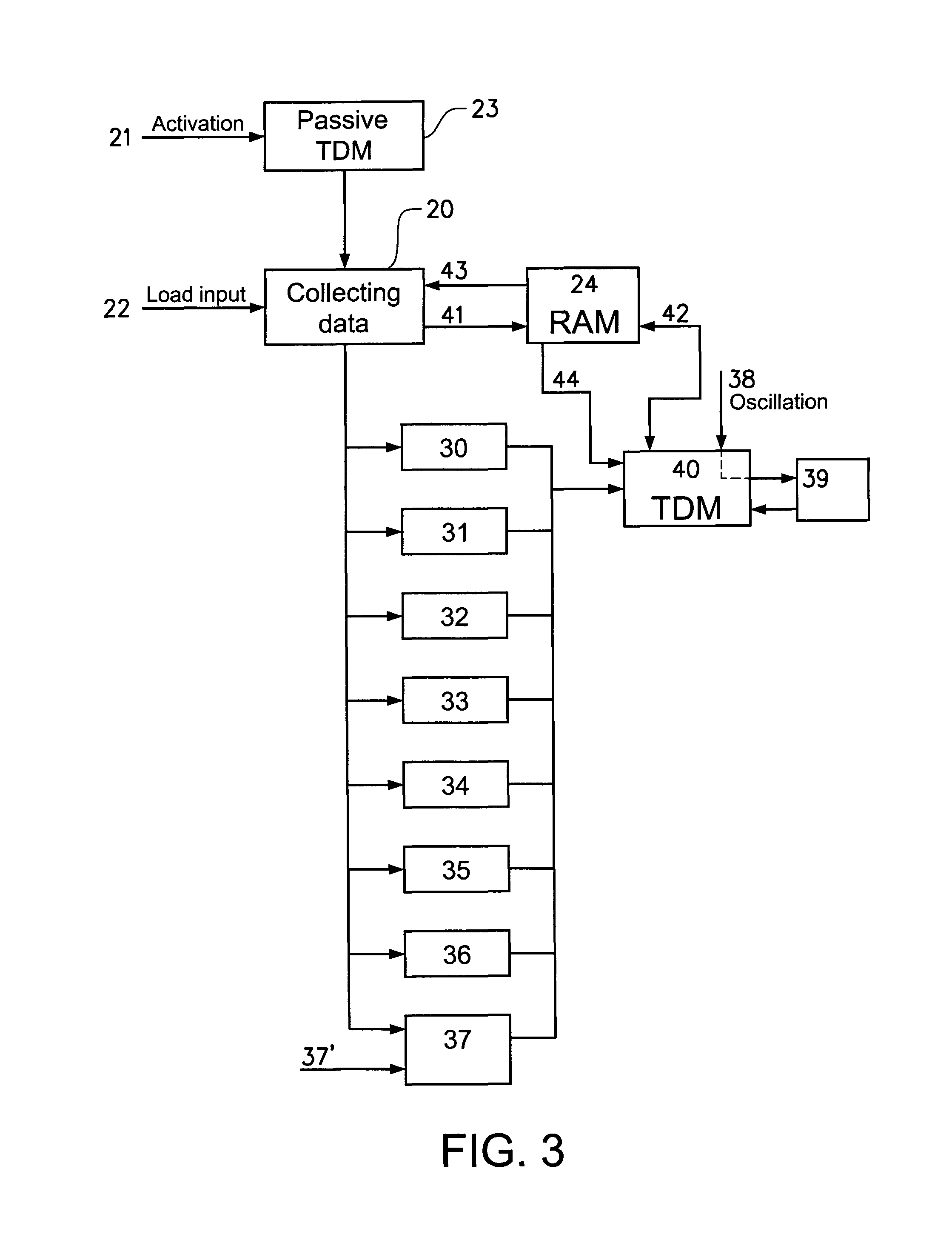
[0014]To further facilitate a smooth start of the tank truck and additional a smooth gear change the torque gradient of the clutch device is limited. The clutch device can be a friction clutch or a torque converter of any kind that fulfil the purpose as a disengagable / engagable torque transmitting element in a drive line. Due to the limited torque gradient the clutch device will disengage and engage slower and therefore enclose a longer period of slip during its disengagement and engagement. Hence a smoother transition from a still standing position by launching the tank truck and between the different gears during a gear change will be realized.
[0018]The inventive method embodiments suggest a tank drive mode to control a drive line of a tank truck. The method will during launch and travel, minimize or even avoid dangerous surging of a fluid in the tank, causing low frequency longitudinal oscillations of the tank truck. Due to the inventive method safety for the driver of the tank truck and the fellow road-users is significantly increased. Further, a cleaning of the tank is simplified, since the need for anti-surging elements in the tank is reduced.
[0026]An improved method to calculate the mass of the tank truck during the launch of the vehicle is suggested. The improved method suggests that in addition to the relation between engine data and drive train data respectively and the vehicle acceleration and / or speed and / or throttle opening, a compensation for the inertial reaction of the fluid is done. This could be a longer sensing period for collecting data for the calculation, and that the longer sensing period permits a compensation of the inertial reaction of the fluid.
[0029]avoiding high engine rotational speeds and or—disabling a brake mode.

Problems solved by technology

Due to the inertial reactions of the fluid, for example during accelerations, retardations, and transportation during poor conditions, such as bumpy and uneven roads, low frequency oscillations of the vehicle might occur.
These longitudinal oscillations of the vehicle are apprehended as very unpleasant by the driver of the vehicle and are also unwanted seen from a safety point of view.
There are several problems with surging inhibiting devices like this one.
Firstly, they can not prevent the occurring of the low frequency longitudinal oscillations of the vehicle.
These solutions can only dampen them.
Secondly, the material usage for these solutions is mostly quite high and makes the vehicle heavier and takes up important transport room.
Thirdly, the extra structure in the tank makes the tank much harder to clean, which especially in a tank for provisions is a problem.
With known methods, the unwanted vehicle oscillations must occur before they can be neutralised, which means that it still will be a period of time as the tank truck is exposed to the low frequency longitudinal oscillations.
Due to the limited torque gradient the clutch device will disengage and engage slower and therefore enclose a longer period of slip during its disengagement and engagement.
Due to the inertial reaction of the fluid such a method will end up false if this is not included in the calculation.
A limiting of the primary braking system (service brakes) is not recommended, due to safety reasons.

Method used


Image

  • Method and device for preventing a surging of fluids in a tank of a tank truck
  • Method and device for preventing a surging of fluids in a tank of a tank truck
  • Method and device for preventing a surging of fluids in a tank of a tank truck

Examples


Embodiment Construction

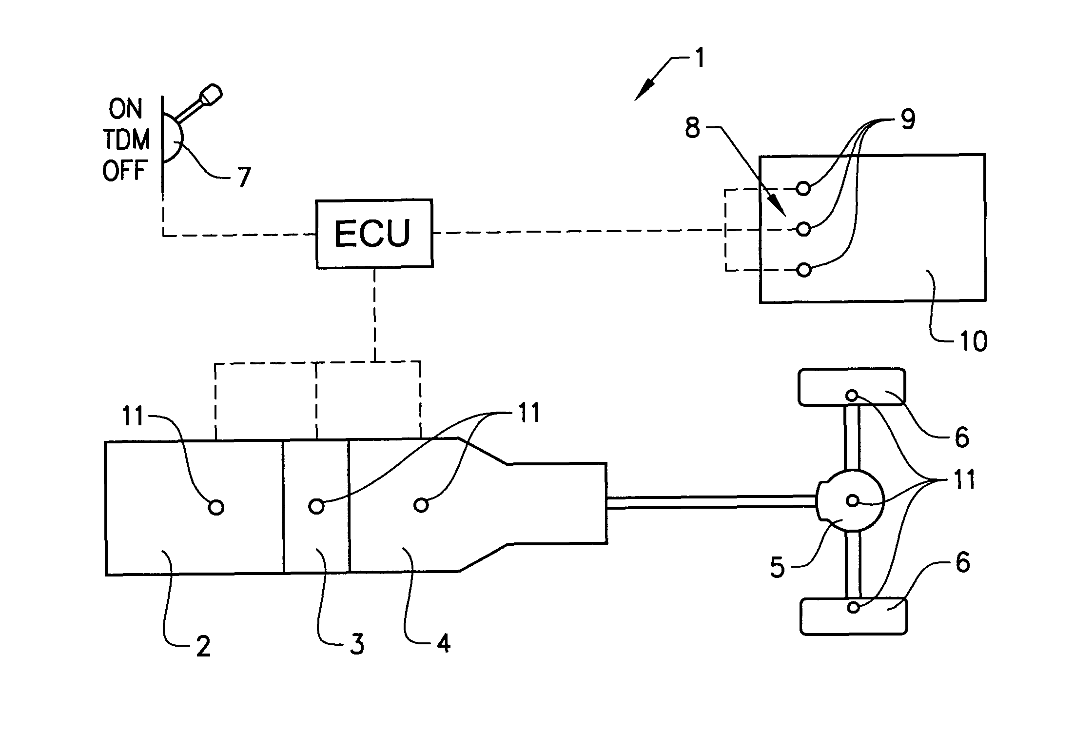
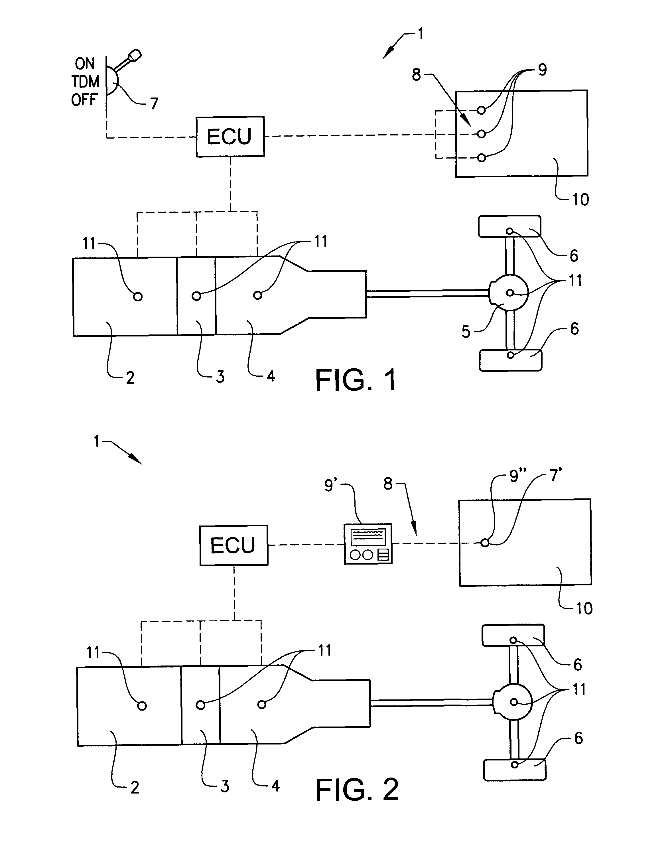
[0043]In FIG. 1 a schematic view of a tank truck 1 according to the invention is shown. The tank truck 1 encloses a drive train with an engine 2, a clutch device 3, a transmission 4, a differential 5 and two wheels 6. The drive train is controlled by an electronic control unit ECU. In accordance with the invention the ECU receives signals from a tank drive mode (TDM) detecting unit 7 in a driver's cabin. To collect data of the tank load status the ECU uses the sensing means 8, which are sensors 9 having access to the tank 10.

[0044]When the driver positions the TDM detecting unit 7 in the position ON a signal is sent to the ECU that TDM is activated. The ECU will then collect relevant data from the sensors 9. Using the collected data and known drive train data the ECU calculates the TDM data, such as launch gear, limited torque gradient for clutch device 3 and engine 2.

[0045]Further sensors 11 are present in the drive train. The sensors 11 monitor the drive train, and through these s...


PUM


Abstract

A method and device for preventing a surging of fluids in a tank of a tank truck, during transportation, the tank truck having a drive train including an internal combustion engine, a clutch device and an automatic or automated transmission device, and the drive train is controlled by an electronic control unit (ECU), which is prepared to receive input data from an arrangement for detecting a tank drive mode and sensors for sensing a load status of the tank truck. The method includes detecting a tank drive mode, calculating a launch gear, and limiting the clutch device torque gradient.

Description

BACKGROUND AND SUMMARY[0001]The present invention relates to a method for preventing a surging of fluids in a tank of a tank truck, during transportation. Said tank truck having a drive train comprising an internal combustion engine, a clutch device and an automatic or automated manual transmission.[0002]It is well known that fluids in a partly filled up tank of a tank truck surges around in the tank during transportation. The surging in the tank influences the vehicle's driving performance. Due to the inertial reactions of the fluid, for example during accelerations, retardations, and transportation during poor conditions, such as bumpy and uneven roads, low frequency oscillations of the vehicle might occur. The acceleration, retardation, and transportation with the vehicle becomes uneven as the longitudinal oscillations acts with or against the wanted acceleration or retardation respectively. These longitudinal oscillations of the vehicle are apprehended as very unpleasant by the ...

Claims


Application Information

Patent Timeline
Patent Type & Authority Patents(United States)
IPC IPC(8): B60W30/18B60W10/10B60W10/11B60W10/06F16H61/02B60W10/02B60P3/22
CPCB60W10/02B60P3/2235B60W10/06B60W10/11B60W30/18027B60W2530/10B60W2560/02B60W2530/209
Inventor ERIKSSON, ANDERSBJERNETUN, JOHAN
Owner VOLVO LASTVAGNAR AB
Learn More