Approach for engine control and diagnostics

a technology of engine control and diagnostics, applied in the direction of electric control, machines/engines, mechanical equipment, etc., can solve the problems of requiring more processing power, and stoichiometry may be a little off, so as to improve emissions performance, improve catalyst performance, and increase the operating window

Active Publication Date: 2015-11-03
FORD GLOBAL TECH LLC
View PDF6 Cites 7 Cited by
  • Summary
  • Abstract
  • Description
  • Claims
  • Application Information

AI Technical Summary

Benefits of technology

[0002]Efficient conversion of exhaust gas emissions in a gasoline engine includes maintaining the catalyst feedgas air-fuel ratio at a narrow window around stoichiometry. However, during actual engine operation, slight excursions away from stoichiometry may occur. To increase the operating window and thus improve emissions performance, catalysts often include ceria to provide a buffer for oxygen storage. To maintain optimal catalyst performance, stored oxygen may be maintained at a desired set point, calibrated based on engine load and temperature, via feedback control of engine air-fuel ratio.
[0006]The present disclosure may offer several advantages. For example, processing resources devoted to the catalyst model may be reduced. Further, emissions control may be improved by maintaining the catalyst at a desired fractional oxidation state. In addition, the evolution of exhaust species, such as HC, NOx and CO, or aggregate oxidants and reductants, may be monitored, and if breakthrough is predicted, an operator of the vehicle may be notified and / or additional engine control operations may be undertaken to control the production of the exhaust species. Another advantage of the present approach is that it offers a non-intrusive catalyst monitor for control and diagnostics, which is less dependent on sensor location and hence will be equally applicable to both partial and full volume catalyst systems. Finally, by tying together the two set-points in this way, controller robustness can be improved while limiting complexity and calibration efforts.

Problems solved by technology

However, during actual engine operation, slight excursions away from stoichiometry may occur.
However, the inventors herein have recognized an issue with the above approach.
Such a model may be difficult to implement and may require more processing power than typically available in an engine controller.

Method used


Image

  • Approach for engine control and diagnostics
  • Approach for engine control and diagnostics
  • Approach for engine control and diagnostics

Examples


Embodiment Construction

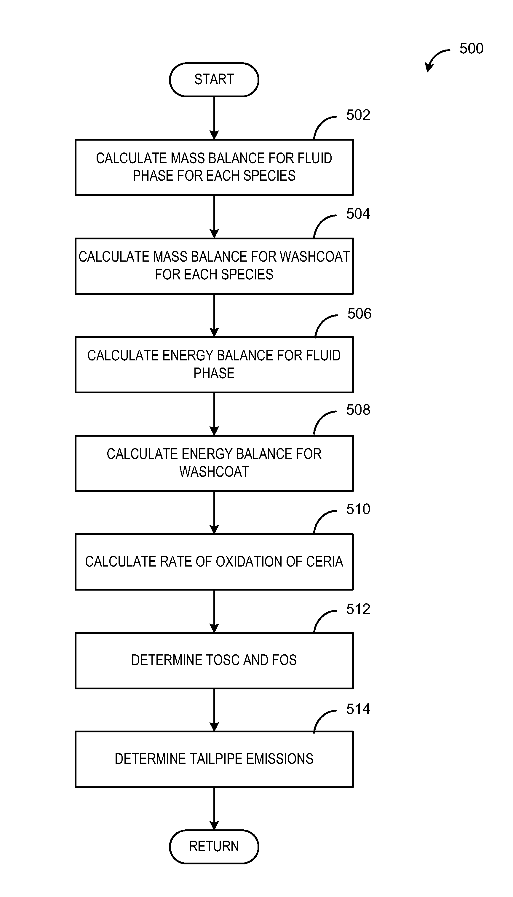
[0015]To reduce the breakthrough of emissions, catalysts may utilize oxygen storage material, for example ceria in the form of cerium oxide, to provide buffer for oxygen during rich or lean excursions. The air-fuel ratio entering the catalyst may be controlled such that the oxidation state of the catalyst is maintained at a desired level. In one example model of the present disclosure, the concentration of various exhaust gas species, such as H2, CO, NOx, HC, and O2, at the inlet through the outlet of the catalyst may be modeled using a simplified low-dimensional model. The model accounts for complex catalyst dynamics, such as diffusion and reaction in the washcoat and catalyst aging, and simplifies the dynamics into a set of axially-averaged model equations. The model equations track the balance of each exhaust species in the fluid phase and in the washcoat of the catalyst. Further, the model compensates for overall energy balance in the fluid phase and the washcoat of the catalyst...


PUM


Abstract

Embodiments for an engine exhaust are provided. In one example, a method comprises adjusting a fuel injection amount based on a fractional oxidation state of a catalyst, the fractional oxidation state based on reaction rates of a plurality of exhaust gas species throughout a catalyst longitudinal axis and a set of axially-averaged mass balance and energy balance equations for a fluid phase and a washcoat of the catalyst, and further based on feedback from a downstream air-fuel ratio sensor. In this way, a simplified catalyst model may be used to control air-fuel ratio.

Description

FIELD[0001]The present disclosure relates to feedback control of air-fuel ratio in an internal combustion engine.BACKGROUND AND SUMMARY[0002]Efficient conversion of exhaust gas emissions in a gasoline engine includes maintaining the catalyst feedgas air-fuel ratio at a narrow window around stoichiometry. However, during actual engine operation, slight excursions away from stoichiometry may occur. To increase the operating window and thus improve emissions performance, catalysts often include ceria to provide a buffer for oxygen storage. To maintain optimal catalyst performance, stored oxygen may be maintained at a desired set point, calibrated based on engine load and temperature, via feedback control of engine air-fuel ratio.[0003]However, the inventors herein have recognized an issue with the above approach. Determining the level of stored oxygen in a catalyst typically involves utilization of a physics-based catalyst model that includes a plurality of partial differential equatio...

Claims


Application Information

Patent Timeline
Patent Type & Authority Patents(United States)
IPC IPC(8): F01N3/00F02D41/02
CPCF02D41/0295F02D41/1441F02D41/1456F02D41/18F02D2200/0814F02D2200/0816F01N11/007
Inventor KUMAR, PANKAJMAKKI, IMAD HASSANFILEV, DIMITAR PETROV
Owner FORD GLOBAL TECH LLC
Why Eureka
Try Eureka