
Light-emitting device and method for manufacturing same

a technology of light-emitting devices and manufacturing methods, which is applied in the direction of semiconductor devices, basic electric elements, electrical equipment, etc., can solve the problems of reducing the light-emitting efficiency and brightness of the leds of a vertical structure, reducing the light-emitting area, and increasing the forward voltage, so as to achieve the effect of preventing the increase of the forward voltage, increasing the current flow path, and enhancing the optical output characteristics

Active Publication Date: 2015-11-03
KOREA UNIV RES & BUSINESS FOUND
View PDF9 Cites 0 Cited by
  • Summary
  • Abstract
  • Description
  • Claims
  • Application Information

AI Technical Summary

Benefits of technology

The present invention relates to a light-emitting device and a method for manufacturing it. The device includes a current-blocking layer and a transparent conductive layer with alternating horizontal and vertical portions, which increases the contact area between the semiconductor layer and the transparent conductive layer and increases the current flow path. The current-blocking layer improves optical output characteristics while the transparent conductive layer prevents an increase of the forward voltage.

Problems solved by technology

This may cause a light-emitting area to be reduced, and a forward voltage may be increased due to current crowding.
In this case, an effective light emission region, a region rather than the ‘n’-type electrode may be reduced, thereby lowering light-emitting efficiency and brightness of the LEDs of a vertical structure.
However, the current-blocking layer reduces an ohmic contact area in the ‘p’-type semiconductor layer due to its insulating characteristic, resulting in increase of a forward voltage.

Method used

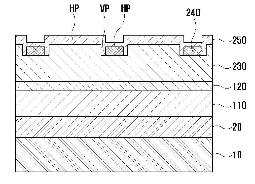
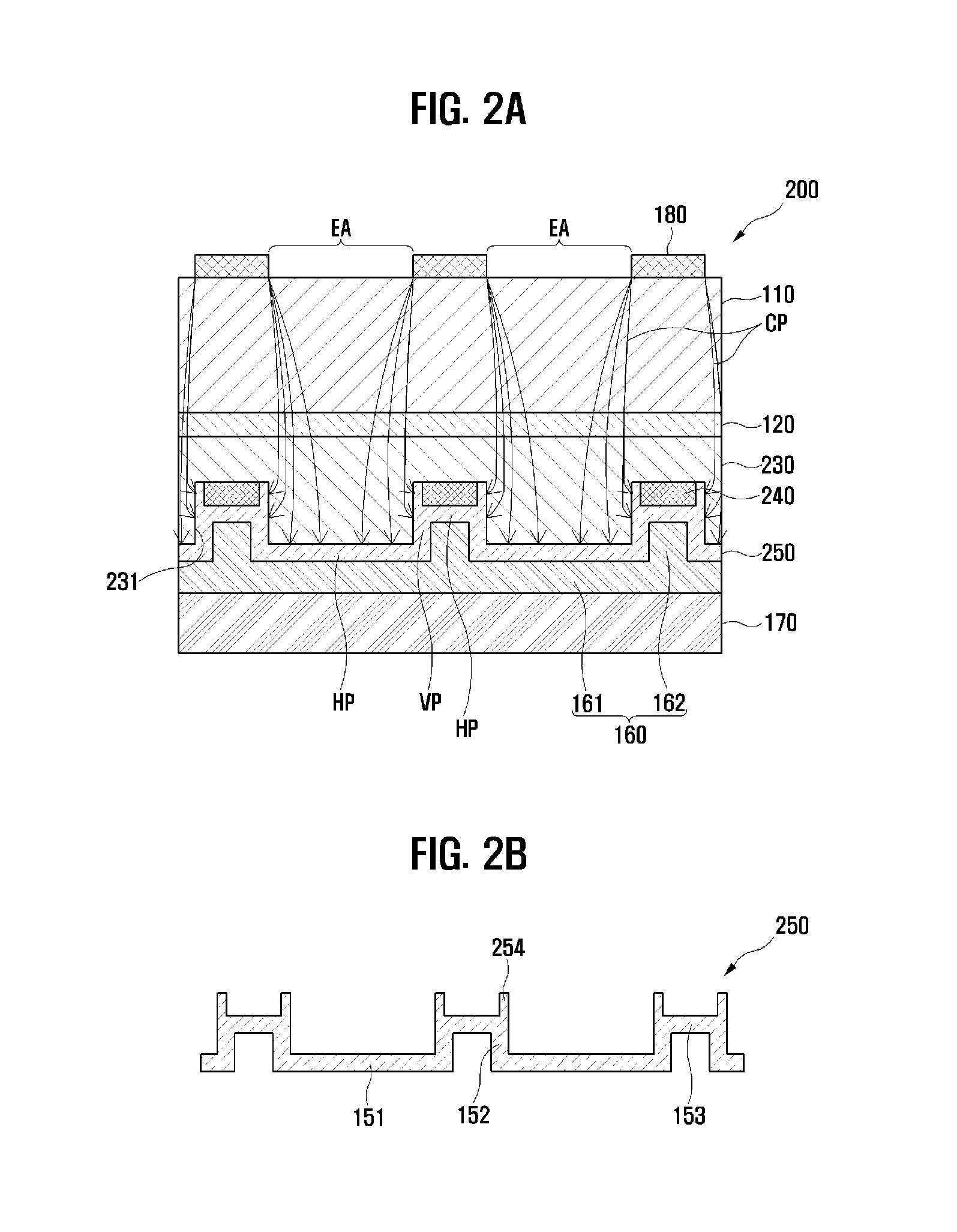

Image

  • Light-emitting device and method for manufacturing same
  • Light-emitting device and method for manufacturing same
  • Light-emitting device and method for manufacturing same

Examples


Embodiment Construction

[0038]Hereinafter, the present invention will be explained in more detail with reference to the attached drawings.

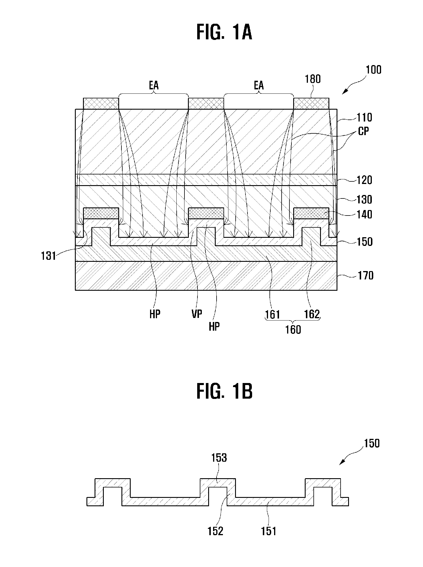
[0039]FIG. 1A is a sectional view of a light-emitting device according to an embodiment of the present invention, and FIG. 1B is a sectional view illustrating a detailed configuration of a transparent conductive layer of FIG. 1A.

[0040]Referring to FIGS. 1A and 1B, the light-emitting device 100 according to an embodiment of the present invention includes a first conductive semiconductor layer 110, an active layer 120, a second conductive semiconductor layer 130, a current-blocking layer 140, a transparent conductive layer 150, a reflective layer 160, a support substrate 170, and an electrode 180. Such light-emitting device 100 may implement light-emitting diodes of a vertical structure.

[0041]The first conductive semiconductor layer 110 may be implemented as an ‘n’-type semiconductor layer. The ‘n’-type semiconductor layer may be selected from semiconductor materials havin...


PUM


Abstract

The present invention relates to a light-emitting device that is capable of preventing an increase in forward voltage while improving optical output characteristics, and to a method for manufacturing same. The light-emitting device comprises: a first conductive semiconductor layer; an active layer which is in contact with the first conductive semiconductor layer; a second conductive semiconductor layer which is in contact with the active layer and which has a patterned groove on a surface opposite the surface that is in contact with the active layer; a current-blocking layer which is formed on a bottom of the groove; a transparent conductive layer which is formed along a surface opposite the surface of the second conductive semiconductor layer that is in contact with the active layer, a sidewall of the groove, and the current-blocking layer; a reflective layer which is formed on a surface opposite the surface of the transparent conductive layer that is in contact with the second conductive semiconductor layer; a support substrate which is formed on a surface opposite the surface of the reflective layer that is in contact with the transparent conductive layer; and an electrode that is patterned on a surface opposite the surface of the first conductive semiconductor layer that is in contact with the active layer.

Description

TECHNICAL FIELD[0001]The present invention relates to a light-emitting device and a method for manufacturing the same, and more particularly, to a light-emitting device capable of enhancing optical output characteristics and capable of preventing increase of a forward voltage, and a method for manufacturing the same.BACKGROUND ART[0002]A light-emitting device is a device to emit light to outside by converting electric energy into light energy. As an example of such light-emitting device, there is a light-emitting diode (LED).[0003]Recently, gallium nitride (GnN)-based LEDs are implemented as LEDs of red, green and blue (RGB) which can implement high brightness and white light owing to a metal organic chemical vapor deposition (MOCVD) of GaN, a growth method such as a molecular-beam epitaxial growth (MBE), and novel processing technology.[0004]Such GnN-based LEDs are applied to a display, a backlight unit, an indoor / outdoor lighting device, etc. As the GnN-based LEDs are applied to a...

Claims


Application Information

Patent Timeline
Patent Type & Authority Patents(United States)
IPC IPC(8): H01L33/14H01L33/60H01L33/42H01L33/38H01L33/40H01L33/20H01L33/00H01L33/44
CPCH01L33/145H01L33/38H01L33/42H01L33/60H01L33/0079H01L33/20H01L33/382H01L33/405H01L33/44H01L2933/0016H01L2933/0058H01L33/0093H01L33/22H01L33/46
Inventor KIM, TAE GEUNKIM, SU-JIN
Owner KOREA UNIV RES & BUSINESS FOUND
Learn More