Neutron generator

Active Publication Date: 2015-11-03
SCHLUMBERGER TECH CORP
View PDF32 Cites 1 Cited by
  • Summary
  • Abstract
  • Description
  • Claims
  • Application Information

AI Technical Summary

Benefits of technology

The present invention is a neutron generator that uses a grounded target electrode and an RF-driven ion source with an external RF antenna. The grounded target electrode reduces the need for high voltage insulation, which facilitates heat removal and avoids depletion of the target under high beam operation. The external RF antenna improves high voltage insulation and allows the RF signal generator to operate at ground potential. Additionally, the RF-driven ion source produces high monatomic hydrogen beam fractions which yield significantly more neutrons per unit beam current as compared to conventional ion sources. These technical effects allow the neutron generator to achieve higher neutron output with improved efficiency and durability.

Problems solved by technology

Because of poor thermal conduction to the exterior (due to the fact that electrical insulators are generally poor thermal conductors), the temperature of the target can increase significantly compared to ambient temperature.
At high ambient temperature, the target can overheat, leading to failure (loss of neutron output) of the neutron generator.

Method used


Image

  • Neutron generator
  • Neutron generator
  • Neutron generator

Examples


Embodiment Construction

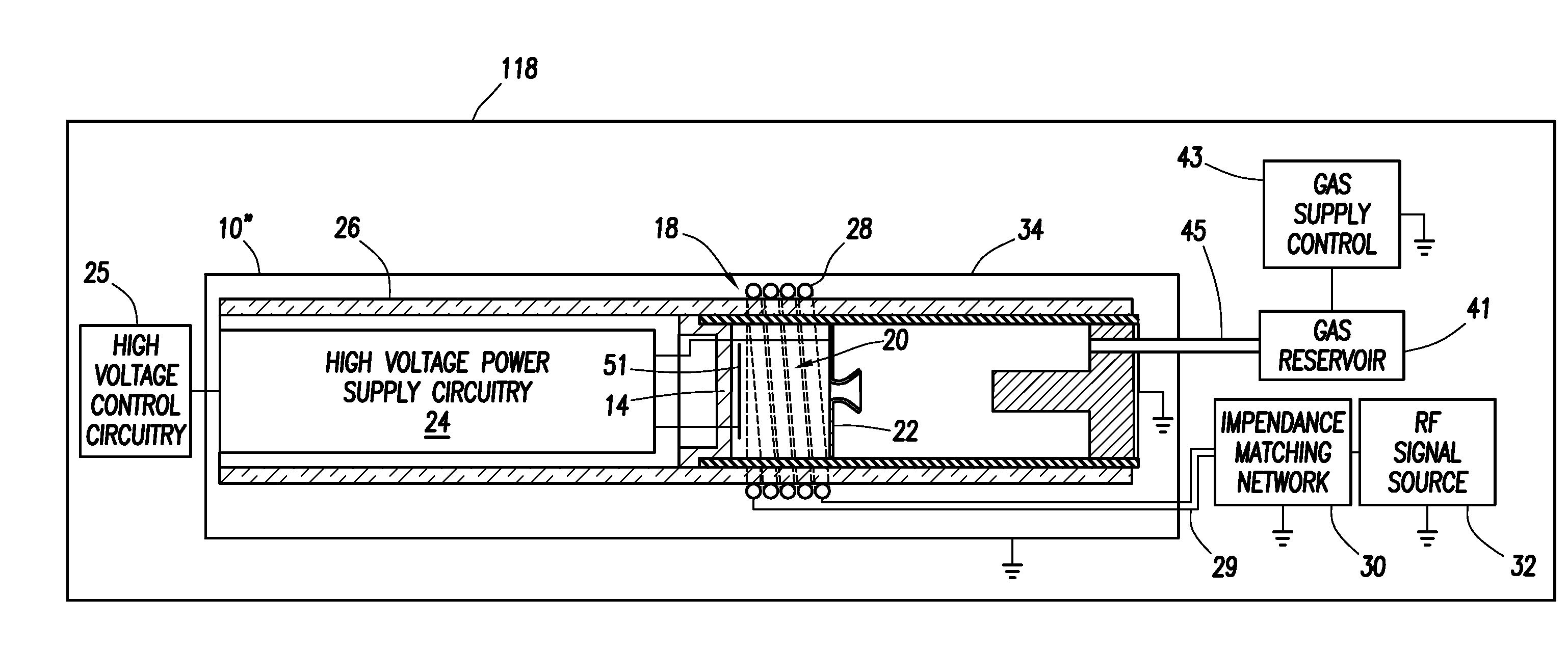
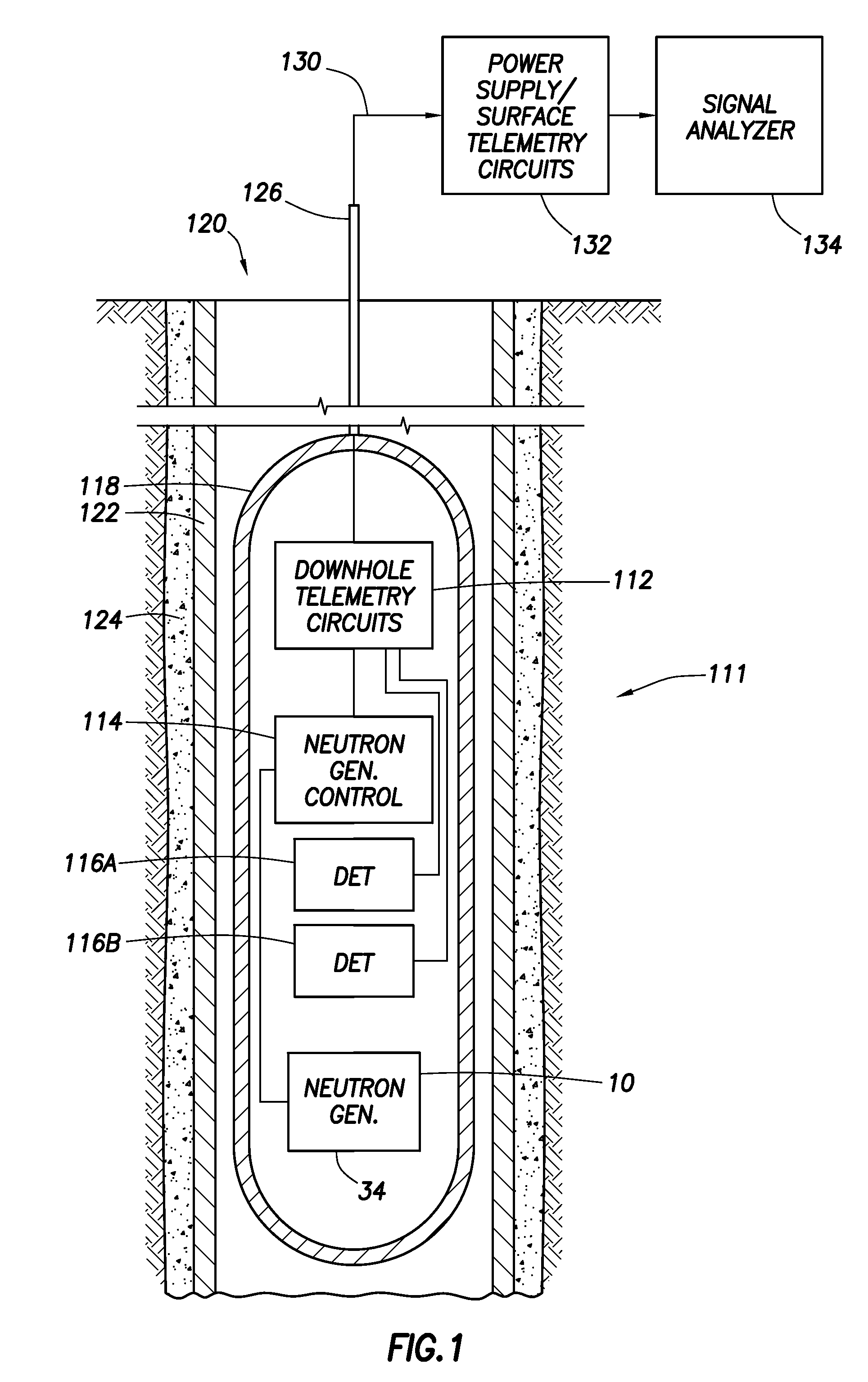
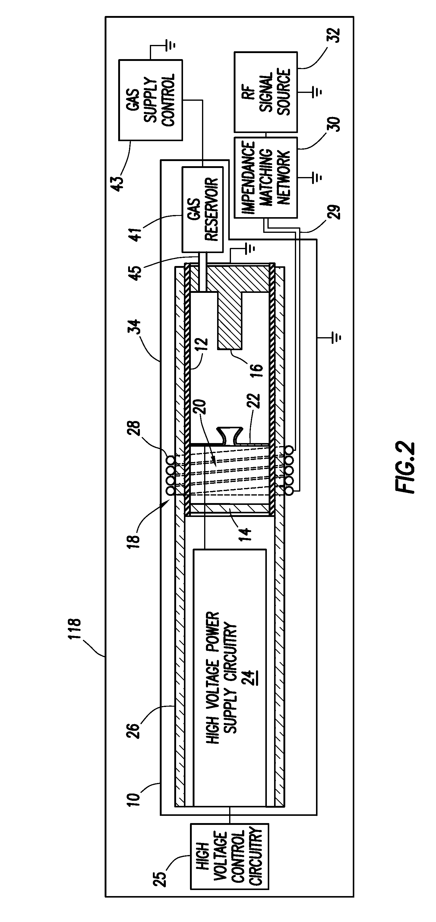
[0032]Turning now to FIGS. 1 and 2, the neutron generator 10 in accordance with the present invention may be used as part of a logging tool 111 as shown. The neutron generator 10 includes a sealed hollow cylindrical tube or envelope 12. An RF-driven ion source 18 is disposed at one end of the sealed envelope 12, and a target electrode 16 is disposed at the other end of the sealed envelope 12 as described below in more detail. The sealed envelope 12 and supporting high voltage electrical components are enclosed in a housing 34, which is referred to below as the Neutron Generator (NG) housing 34. The NG housing 34 and supporting low voltage electrical circuit components 114 as well as other system components (e.g., downhole telemetry circuits 112 and at least one radiation detector (for example, two shown as 116A, 116B)) are housed in a sonde 118 that is configured to be moved through a borehole 120. The borehole 120 is illustrated as including a steel casing 122 and a surrounding cem...


PUM


Abstract

A neutron generator includes a sealed envelope providing a low pressure environment for a gas of hydrogen isotope(s). One end of the envelope defines an ion source chamber. A target electrode is disposed at the other end of the envelope. An extraction electrode is spaced apart from the target electrode by an accelerating gap. The extraction electrode bounds the ion source chamber. An RF antenna is disposed external to the sealed envelope in the vicinity of the ion source chamber. The RF antenna is used to transmit time-varying electromagnetic fields within the ion source chamber for producing plasma therein. The extraction electrode operates at a positive high voltage potential and the target electrode operates at or near ground potential in order to provide an electric field gradient that accelerates ions of the plasma towards the target electrode to induce collisions of ions with target material, thereby causing fusion reactions that generate and emit neutrons from the target material. High voltage insulation is disposed between the RF antenna and both the ion source chamber and the extraction electrode for electrically insulating the RF antenna operating at or near ground potential from the high voltages of the ion source chamber and the extraction electrode.

Description

BACKGROUND OF THE INVENTION[0001]1. Field of the Invention[0002]This invention relates to neutron generating systems and more particularly pertains to sealed-tube neutron generators especially adapted to traverse the narrow confines of a well or borehole, although useful in a variety of other applications.[0003]2. The Related Art[0004]The use of a generator of high energy neutrons has been known for a long time for neutron-gamma ray or neutron-neutron logging in oil well logging tools. Accordingly, for illustrative purposes, the invention is described in more complete detail in connection with a sealed-tube neutron generator suitable for use in a well logging tool.[0005]Sealed-tube neutron generators usually have four major features:[0006](i) a gas source to supply the reacting elements, such as deuterium and tritium;[0007](ii) an ion source that strips electrons from the gas molecules, thus generating plasma of electrons and positively charged ions;[0008]iii) a target impregnated w...

Claims


Application Information

Patent Timeline
IPC IPC(8): H05H3/06G01V5/10G21B1/11
CPCH05H3/06G01V5/10G21B1/11Y02E30/10
Inventor PERKINS, LUKE T.
Owner SCHLUMBERGER TECH CORP
Why Eureka
Try Eureka