Vertical power MOSFET having planar channel and its method of fabrication

a technology of power mosfet and planar channel, which is applied in the direction of basic electric elements, electrical apparatus, and semiconductor devices, etc., can solve the problems of reducing on-resistance, reducing breakdown voltage, and reducing on-resistance, so as to reduce recovery time, reduce the recovery time, and accelerate the removal of stored charge

Active Publication Date: 2015-11-10
MAXPOWER SEMICON INC
View PDF12 Cites 6 Cited by
  • Summary
  • Abstract
  • Description
  • Claims
  • Application Information

AI Technical Summary

Benefits of technology

[0013]Both the vertical portion of the gate and the field plate help to deplete the N-layer laterally when the MOSFET is off to increase the breakdown voltage. The vertical portion of the gate also accumulates electrons along the N-type layer sidewalls across from the P-well when the MOSFET is on to lower the on-resistance. Therefore, since the JFET region (between the P-well and trench) can be made narrower without unduly constraining the current path, the cells may be smaller. Also, since the N-type layer can be relatively highly doped without reducing the breakdown voltage, the on-resistance is further lowered. The combined effect of the vertical portion of the gate, the field plate, the relatively heavy doped N-type layer, and a reduced thickness N-type drift layer provides an increased breakdown voltage, lower on-resistance, and a lower cost per die (since the lower on-resistance per unit area allows each die to be made smaller). The structure allows a higher density of cells (including strips) due to the lower on-resistance per unit area, enabling a greater current handling capability per unit area.
[0018]If the MOSFET is used with an alternating voltage, the MOSFET's PN diode will conduct when the drain is more negative than the source. When the polarity reverses and the diode is reverse biased, there is a stored charge that must be removed prior to the MOSFET being fully turned off after the gate is biased to an off state. Since there is a higher dopant level in the N-type layer, this stored charge is removed faster, enabling a faster switching time. In other words, the MOSFET structure lowers the recovery time after the PN diode is biased on.

Problems solved by technology

However, due to the required low doping of the thick drift layer, the on-resistance suffers.
Increasing the doping of the drift layer reduces the on-resistance but lowers the breakdown voltage.
However, increasing the spacing Y results in an increase in cell pitch and the active area.
Therefore, this tradeoff results in a limited improvement in Rsp.

Method used


Image

  • Vertical power MOSFET having planar channel and its method of fabrication
  • Vertical power MOSFET having planar channel and its method of fabrication
  • Vertical power MOSFET having planar channel and its method of fabrication

Examples


Embodiment Construction

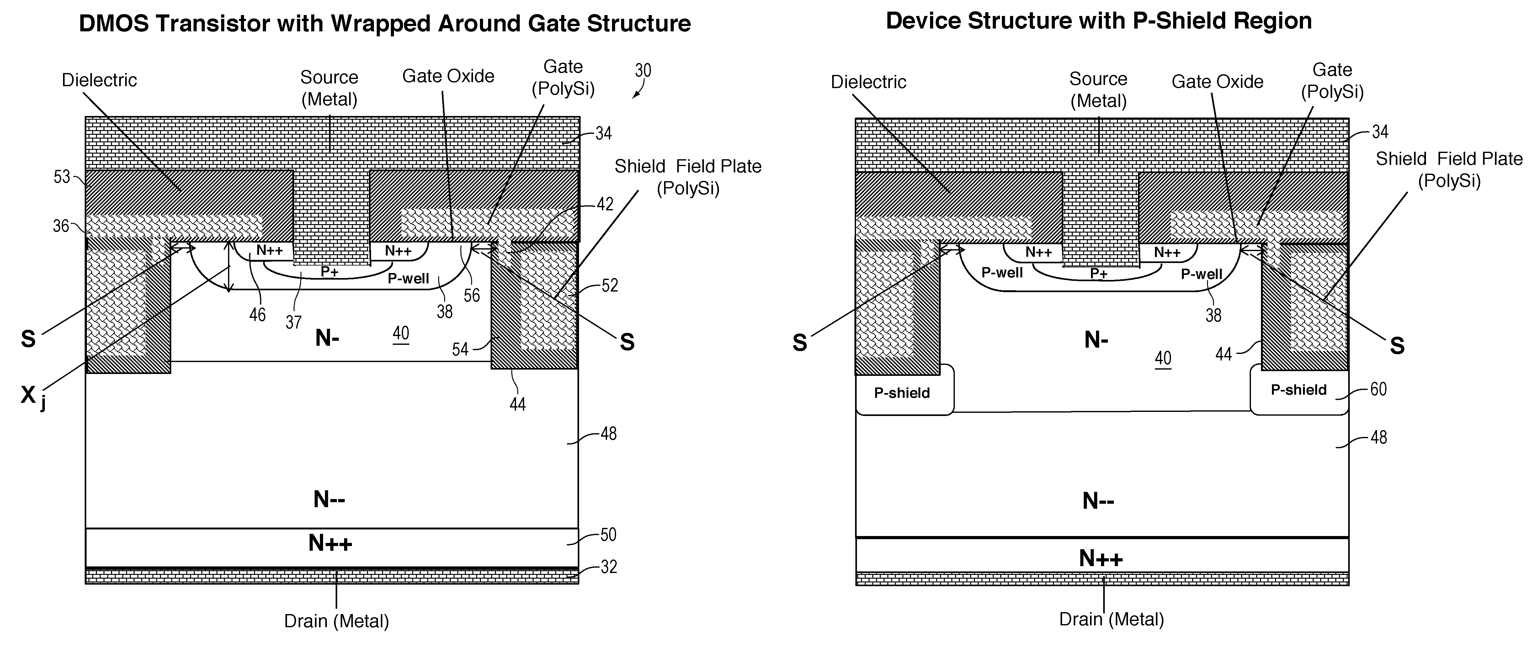
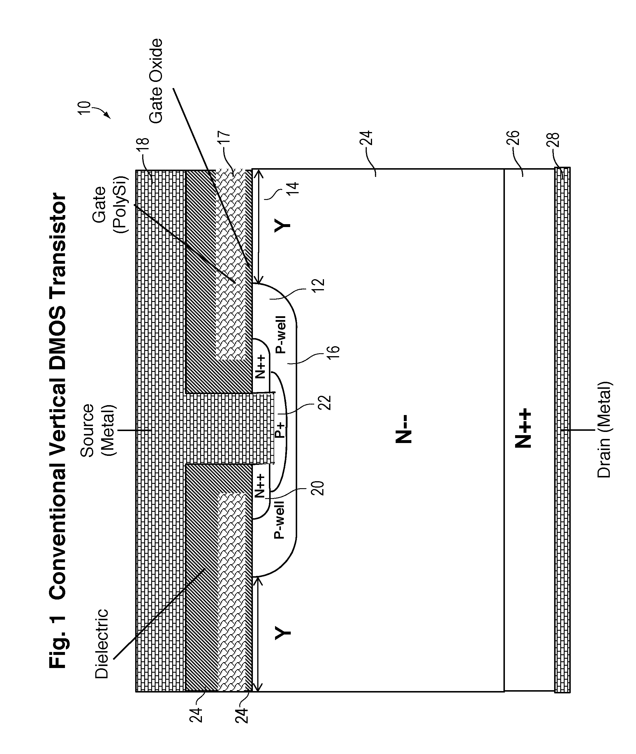
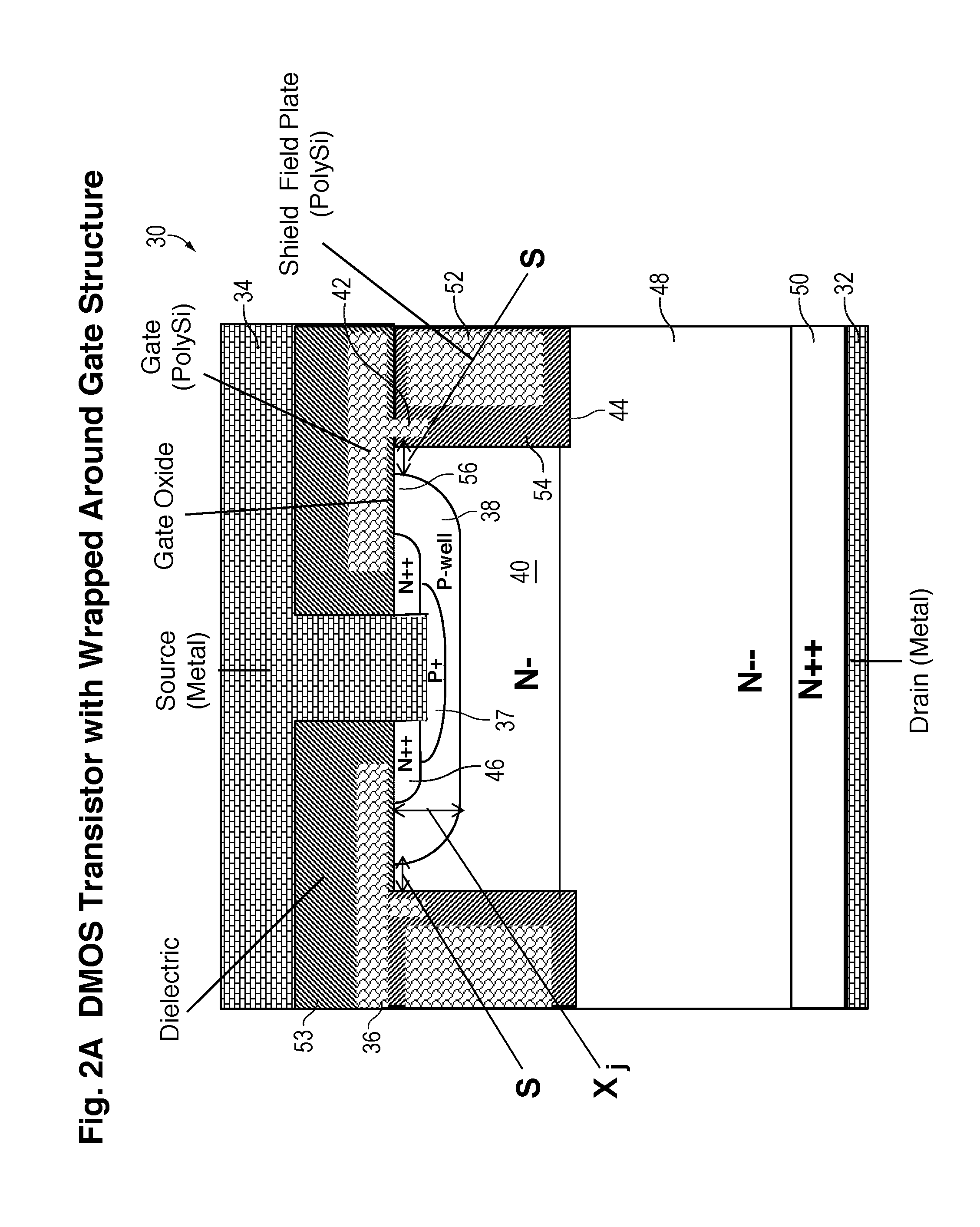
[0058]FIG. 2A is a cross-sectional view of a single vertical MOSFET cell 30 in an array of identical contiguous MOSFET cells connected in parallel in accordance with one embodiment of the invention. FIGS. 8A-8C, described later, illustrate various configurations of the cells, which include strips and closed cells. In the cross-sectional views, the various regions are not drawn to scale for ease of illustration. The simulation diagrams of FIGS. 7A and 7B show more accurate relative dimensions.

[0059]In FIG. 2A, the width of the cell 30 shown is about 5-15 microns. The cell 30 may have a breakdown voltage exceeding 600 volts, and the number of cells 30 in an array of identical cells determines the current handling ability, such as 20 Amps. The array of cells may be in strips, squares, hexagons, or other known shapes.

[0060]In one typical application, a load is connected between the bottom drain electrode 32 and a positive voltage supply, and the top source electrode 34 is connected to g...


PUM


Abstract

A power MOSFET cell includes an N+ silicon substrate having a drain electrode. A low dopant concentration N-type drift layer is grown over the substrate. An N-type layer, having a higher dopant concentration than the drift region, is then formed and etched to have sidewalls. A P-well is formed in the N-type layer, and an N+ source region is formed in the P-well. A gate is formed over the P-well's lateral channel and has a vertical extension next to the top portion of the sidewalls. A positive gate voltage inverts the lateral channel and increases the conduction along the sidewalls to reduce on-resistance. A vertical shield field plate is also located next to the sidewalls and extends virtually the entire length of the sidewalls. The field plate laterally depletes the N-type layer when the device is off to increase the breakdown voltage.

Description

CROSS REFERENCE TO RELATED APPLICATIONS[0001]This application is a continuation-in-part of U.S. application Ser. No. 14 / 338,303, filed Jul. 22, 2014, and claims priority from U.S. provisional application Ser. No. 61 / 935,707, filed Feb. 4, 2014, by Jun Zeng et al., and also U.S. provisional application Ser. No. 62 / 079,796, filed Nov. 14, 2014, by Jun Zeng et al., incorporated herein by reference.FIELD OF INVENTION[0002]The present invention relates to power MOSFETs and, in particular, to a vertical transistor having a planar DMOS portion and a vertical conduction portion.BACKGROUND[0003]Vertical MOSFETs are popular as high voltage, high power transistors due to the ability to provide a thick, low dopant concentration drift layer to achieve a high breakdown voltage in the off state. Typically, the MOSFET includes a highly doped N-type substrate, a thick low dopant concentration N-type drift layer, a P-type body layer formed in the drift layer, an N-type source at the top of the body l...

Claims


Application Information

Patent Timeline
Patent Type & Authority Patents(United States)
IPC IPC(8): H01L29/423H01L29/40H01L29/732H01L29/78H01L29/06H01L29/739H01L29/10
CPCH01L29/407H01L29/0692H01L29/1095H01L29/7395H01L29/7811H01L29/7397H01L29/0634H01L29/0834H01L29/41766H01L29/42376H01L29/66727H01L29/66734H01L29/7396H01L29/7802H01L29/0623H01L29/402H01L29/4236H01L29/7813H01L29/404
Inventor ZENG, JUNDARWISH, MOHAMED N.PU, KUISU, SHIH-TZUNG
Owner MAXPOWER SEMICON INC
Why Eureka
Try Eureka