Carriage to transport a ladle and to transfer molten metal into equipment for pouring and transportation line for transporting molten metal

a technology for transportation lines and ladles, which is applied in the direction of manufacturing tools, lighting and heating equipment, furniture, etc., can solve the problems of complex installation of plants, unfavorable environmental protection, and the possibility of falling off the ladle accidentally, so as to reduce the cycle time, reduce the investment cost, and minimize the size of the equipment

Active Publication Date: 2015-11-17
SINTOKOGIO LTD +1
View PDF11 Cites 1 Cited by
  • Summary
  • Abstract
  • Description
  • Claims
  • Application Information

AI Technical Summary

Benefits of technology

[0009]The transportation line for transporting molten metal of the present invention can produce effects such as reducing the investment cost by minimizing the size of the equipment, maintaining the temperature of the molten metal, and reducing the cycle time by shortening the time for transporting the molten metal. Further, by introducing the transportation line for transporting the molten metal of the present invention the space for the transportation line can be minimized.

Problems solved by technology

However, the method disclosed in Patent Document 1 has problems, for example, in that workers come close to a dangerous area of the molten metal, which has a high temperature, or there is a chance that the lifted ladle might accidentally fall.
But the method has its own defects, for example, of the kinds in which the investment cost becomes higher if the installation of the plant becomes complex, depending on the layout of a melting furnace and equipment for pouring, and in which the temperature of the molten metal drops or the cycle time for pouring the molten metal becomes longer because the time required for the transport becomes longer.

Method used


Image

  • Carriage to transport a ladle and to transfer molten metal into equipment for pouring and transportation line for transporting molten metal
  • Carriage to transport a ladle and to transfer molten metal into equipment for pouring and transportation line for transporting molten metal
  • Carriage to transport a ladle and to transfer molten metal into equipment for pouring and transportation line for transporting molten metal

Examples


Embodiment Construction

[0016]Below the transfer carriage in one embodiment of the present invention is explained based on the drawings.

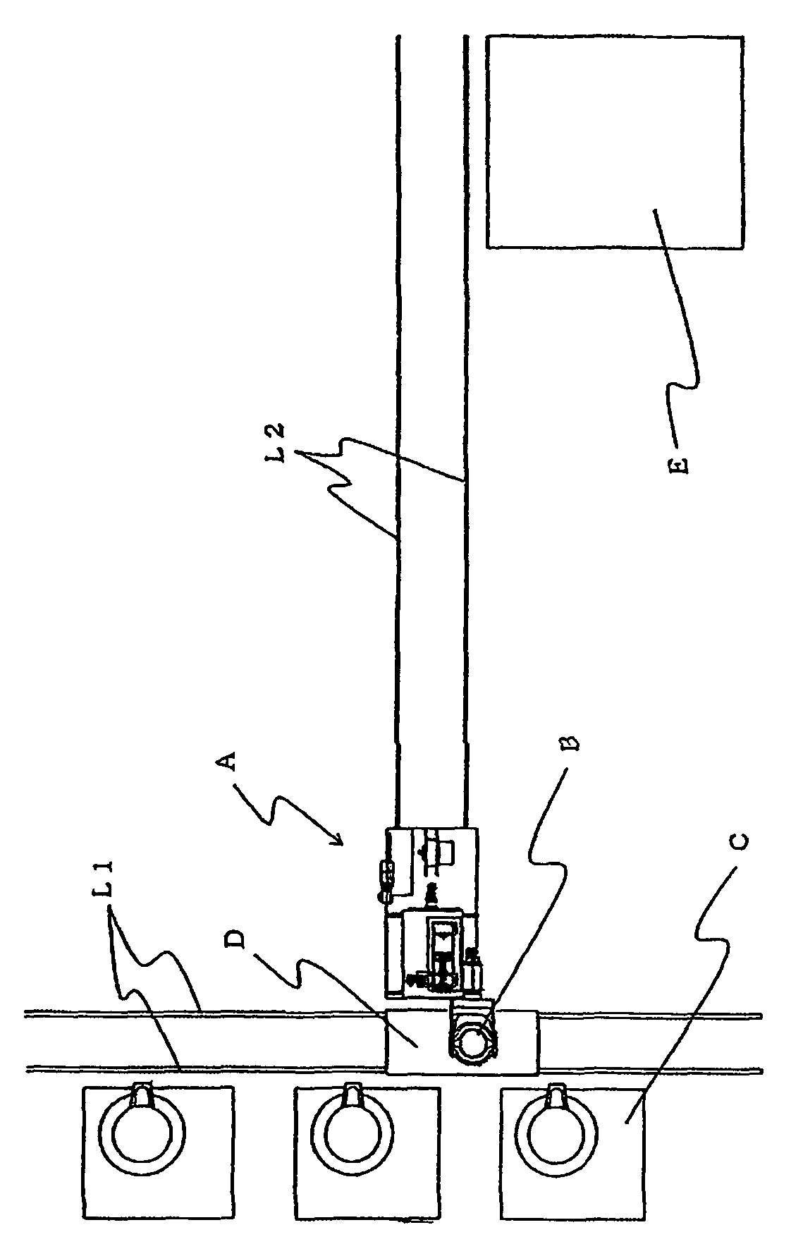
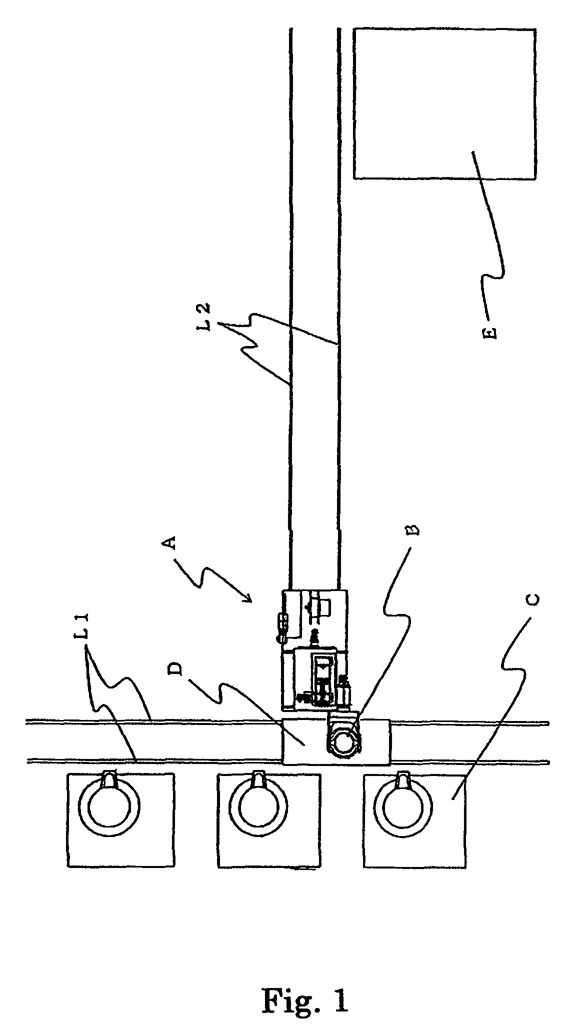
[0017]FIG. 1 is a schematic view of the transportation line for transporting molten metal using a transfer carriage and a receiving carriage in one embodiment of the present invention.

[0018]As shown in FIG. 1, the transportation line for transporting molten metal is constituted in a way such that the rails for the receiving ladle that receives the molten metal (hereafter “rails for the receiving ladle”) L1 are laid in front of the melting works C, and the rails for transporting a ladle L2 are laid in the direction that is perpendicular to the rails for the receiving ladle L1, on which the receiving carriage D runs. Also, the rails for transporting a ladle L2 are laid alongside the pouring works E. The transfer carriage A runs on the rails for transporting a ladle L2.

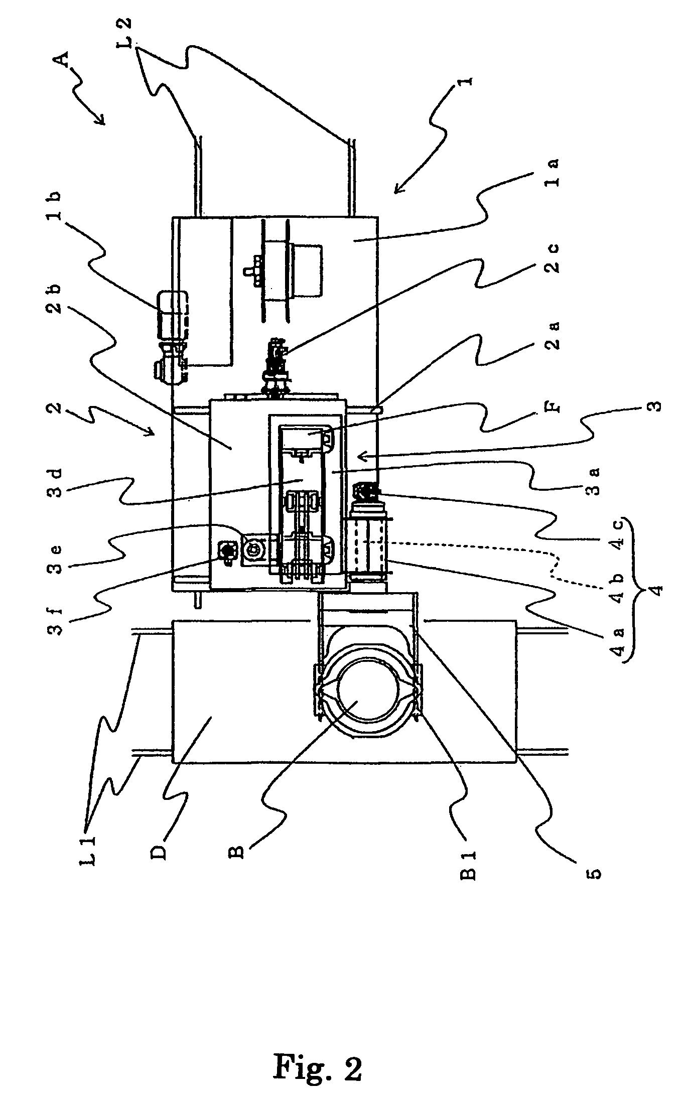
[0019]FIGS. 2 and 3 illustrate how the transfer carriage replaces the ladle on the receiving carriage. In FI...


PUM

PropertyMeasurementUnit
L-Shapeaaaaaaaaaa
temperatureaaaaaaaaaa
weightaaaaaaaaaa

Abstract

The present invention provides a carriage to transport a ladle and to transfer molten metal into equipment for pouring (hereafter, transfer carriage) whereby the investment cost can be reduced by having the equipment made compact, and the temperature of the molten metal can be maintained high, and the cycle time can be reduced, because the time to transport the molten metal can be less. Further, the present invention provides a transportation line for transporting the molten metal. This line requires a smaller space for its installation. The transfer carriage of the present invention comprises a transportation means that runs along the rails for transporting a ladle; a shifting means disposed on the transportation means, which shifting means moves in the direction that is perpendicular to the rails for transporting a ladle; a lifting mechanism attached to a pillar set upright on the shifting means, a tilting means disposed at a lifting member of the lifting mechanism; and a ladle-holding member that is supported by the tilting means at the axis of the tilting means, which member is tilted by the tilting means, and which can hold or release a receiving ladle, wherein the carriage transfers the molten metal in the receiving ladle into the ladle for pouring.

Description

FIELD OF THE INVENTION[0001]This invention relates to a carriage used in a foundry. It transports a ladle that contains molten metal and transfers the molten metal to another ladle. It also relates to a transportation line for transporting the molten metal.TECHNICAL BACKGROUND[0002]Conventionally, in a foundry a cast product is manufactured by a process where molten metal that is melted in melting works is at first transported to pouring works, and there the molten metal is poured into a mold. A ladle is used as a container that transports the molten metal. There was a method to transport a ladle wherein the ladle first received the molten metal from the melting works and then it was transported by a crane to the pouring works where the molten metal was supplied to the equipment for pouring of the pouring works. (See Paragraph 0002 of Patent Document 1.)PRIOR-ART DOCUMENT[0003]Patent Document 1: Published Japanese patent application, Publication No. 2004-230439SUMMARY OF THE INVENTI...

Claims


Application Information

Patent Timeline
Patent Type & Authority Patents(United States)
IPC IPC(8): F27B14/02B22D41/12
CPCB22D41/12
Inventor TAMOTSU, HIROYUKI
Owner SINTOKOGIO LTD
Why Eureka
Try Eureka