

Method for producing a turbine rotor of an exhaust gas turbocharger, and use of a turbine rotor
a technology of turbine rotor and exhaust gas, which is applied in the direction of machines/engines, solid-state diffusion coating, mechanical apparatus, etc., can solve the problems of adversely affecting the surface of the turbine wheel, high temperature properties, and are typically not resistant to oxidation, and achieves low density and low cost. , the effect of high production efficiency
- Summary
- Abstract
- Description
- Claims
- Application Information
AI Technical Summary
Benefits of technology
Problems solved by technology
Method used
Image

Examples
Embodiment Construction
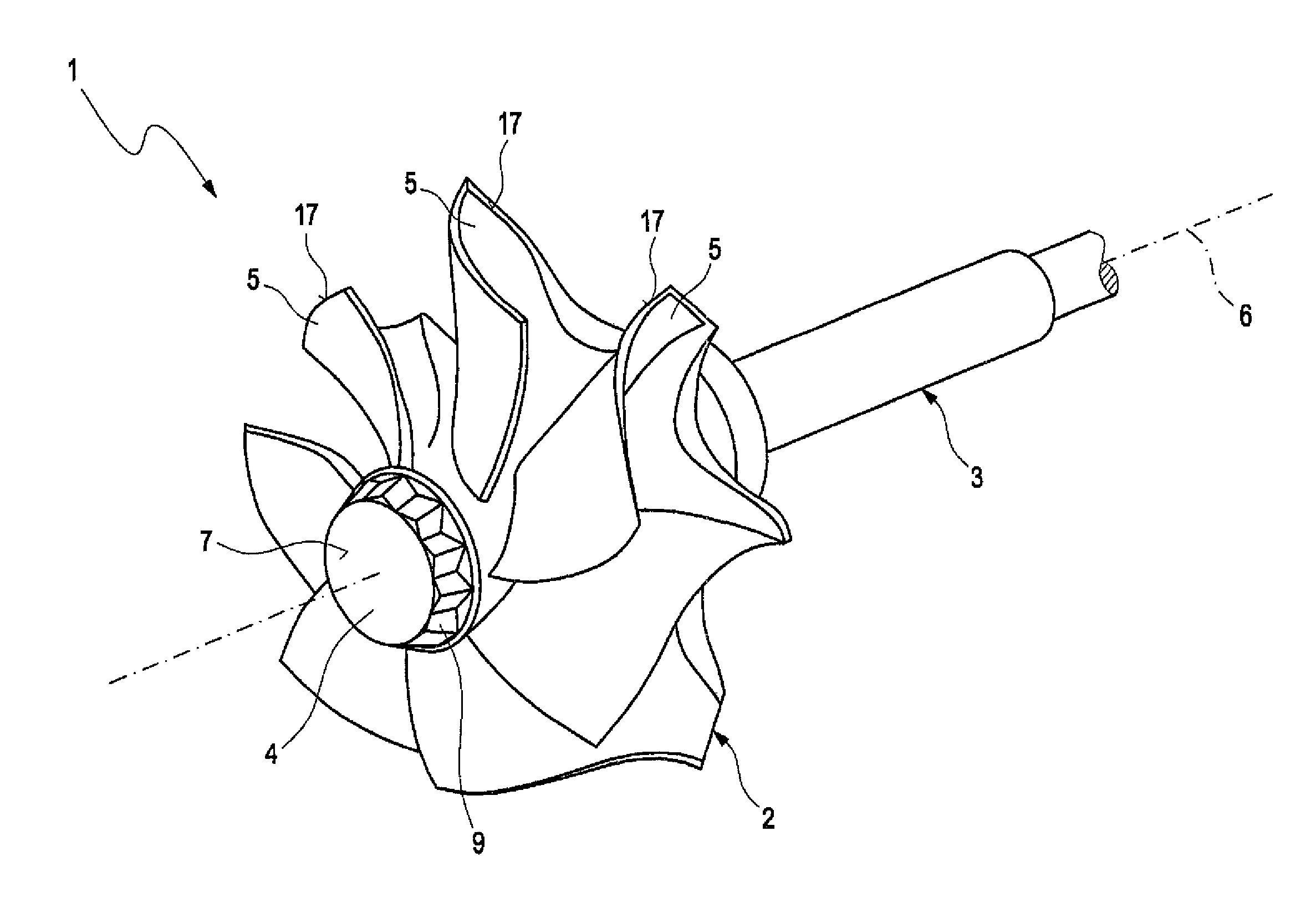
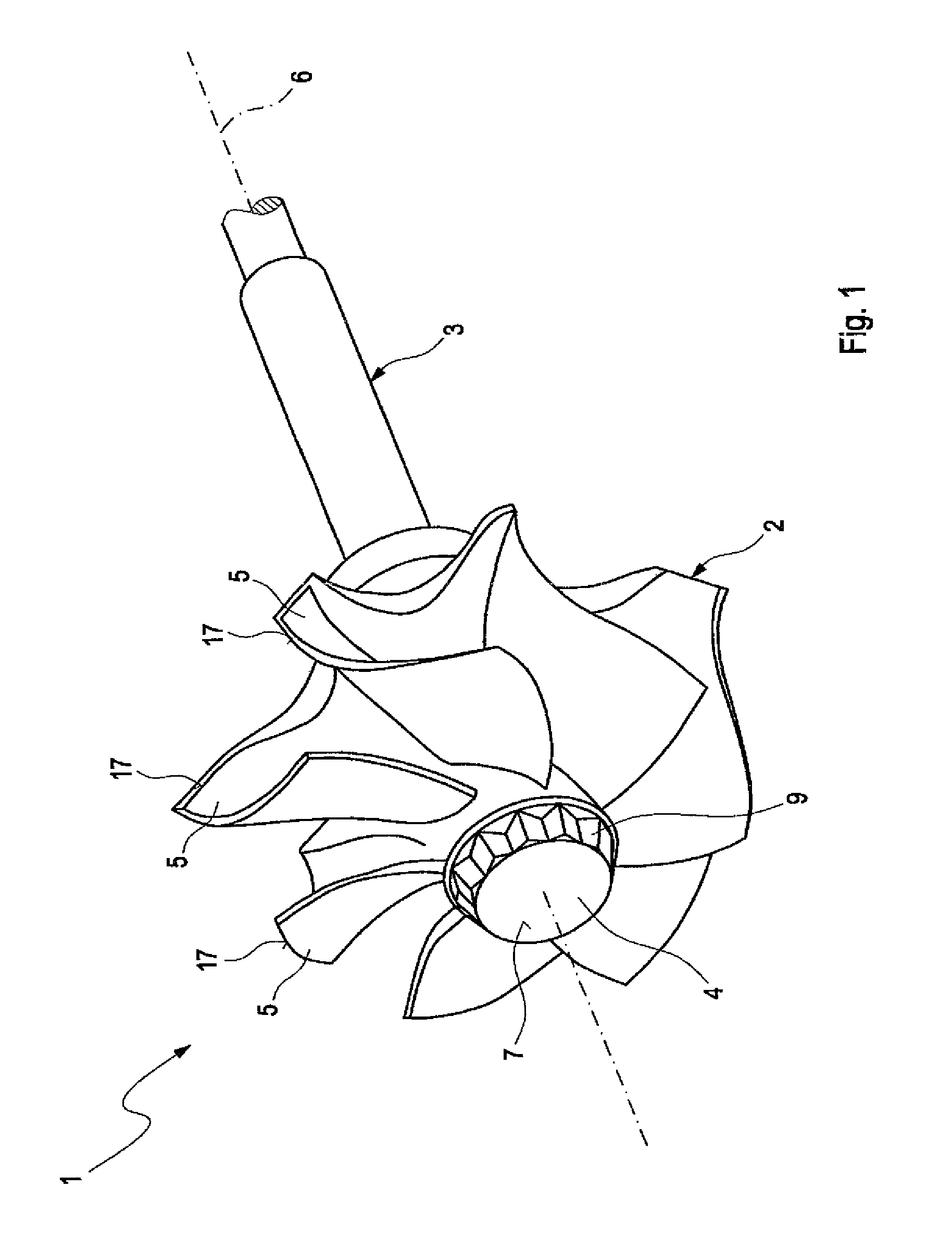
[0022]FIG. 1 shows a turbine rotor 1 of an unillustrated exhaust gas turbocharger. The turbine rotor 1 includes a turbine wheel 2 and a shaft 3. The turbine rotor 1 is part of the exhaust gas turbocharger which is associated with an internal combustion engine. The turbine rotor 1 is normally rotatably mounted in a turbine housing, wherein an impeller of a compressor is operatively connected with the turbine wheel 2 via the shaft 3. The turbine wheel 2 is composed of a hub 4 and a plurality of turbine blades 5, of which only some turbine blades are labeled with reference numerals by way of example. The turbine blades 5 extend starting from the hub 4—in relation to a rotational axis 6 of the turbine rotor 1—outward in a radial direction. The turbine wheel 2 is, for example, made of an aluminum alloy, for example a titanium-aluminum alloy, in particular a titanium aluminide. Conversely, the shaft 3 is made of steel, for example, a low-alloy steel, in particular 34CrMo4. The shaft 3 is ...
PUM
| Property | Measurement | Unit |
|---|---|---|
| temperature | aaaaa | aaaaa |
| temperature | aaaaa | aaaaa |
| density | aaaaa | aaaaa |
Abstract
Description
Claims
Application Information