Composite gear blank

a composite gear and gear blank technology, applied in the field of composite gear blanks, can solve the problems of not meeting the stringent requirements of eps systems in larger engine cars and/or eps-systems located, and giving any detailed information,

Inactive Publication Date: 2015-12-08
QUADRANT EPP
View PDF36 Cites 7 Cited by
  • Summary
  • Abstract
  • Description
  • Claims
  • Application Information

AI Technical Summary

Benefits of technology

[0076]In yet a further embodiment, step a) comprises providing an assembly of a plurality of rigid centerpieces lined up on an elongated holder element, each pair of adjacent centerpieces being separated by a spacer element. The plurality of composite gear blanks thus formed is then disassembled. In general, this allows production of a plurality of composite gear blanks in one given molding cycle and thus may contribute to lower the production costs.

Problems solved by technology

However, DE 101 27 224 A1 does not give any detailed information on how to carry out the casting or injection molding processes nor does it show any comparison of the results obtained by the two methods.
However, it has been found that the strength of the plastic to metal connection of the composite gear blanks produced according to the various prior art methods does not meet some of the stringent requirements for EPS systems in larger engine cars and / or for EPS-systems located “under the hood”, i.e. close to the engine where the operating temperature is typically around 120° C.

Method used


Image

  • Composite gear blank
  • Composite gear blank
  • Composite gear blank

Examples


examples

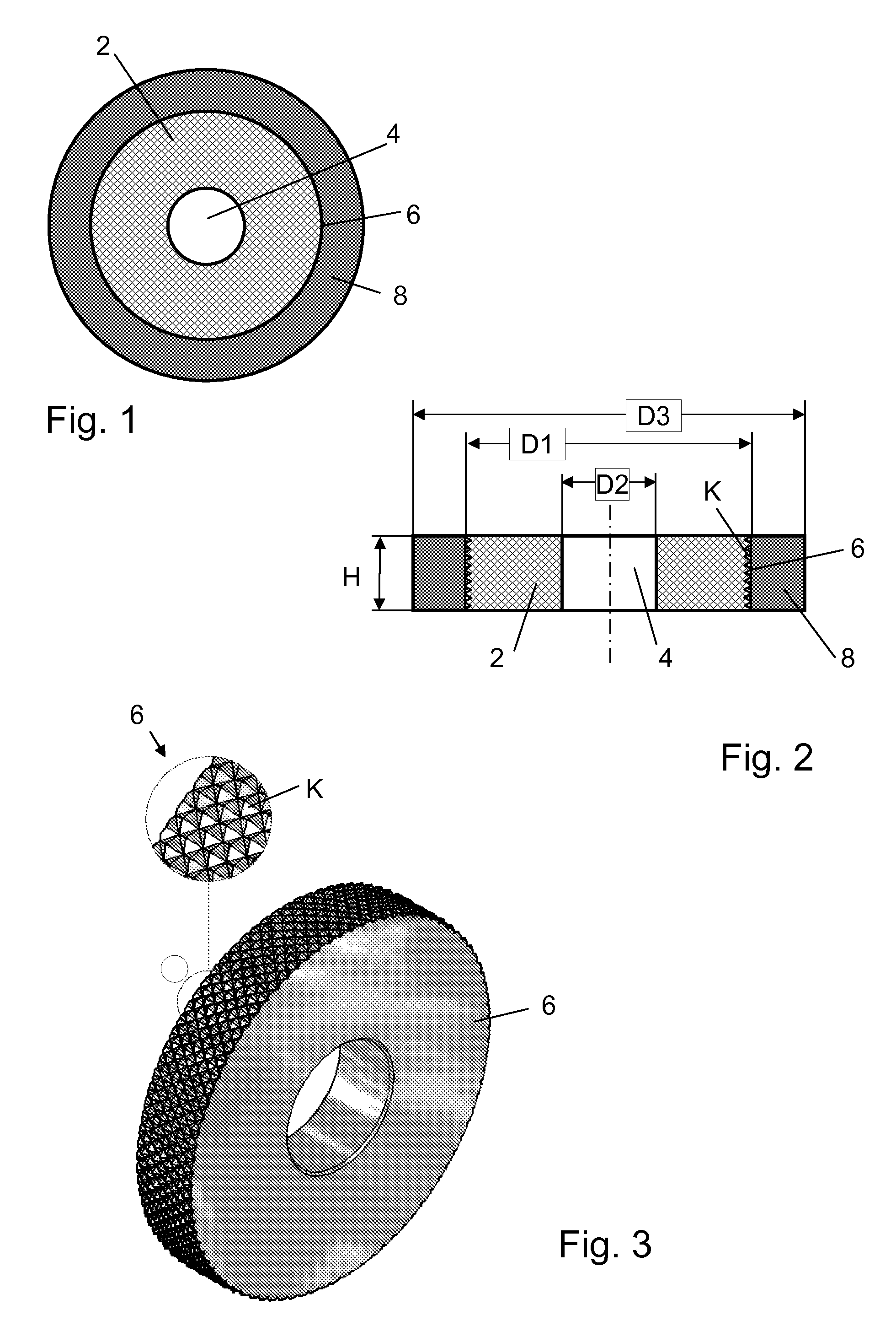
[0115]The following examples refer to composite gear blanks each comprising a ring-shaped centerpiece made of S25C carbon steel (also denoted as 1.1158 steel, DIN17200, CK25) having the following dimensions:[0116]outer diameter of centerpiece: D1=75 mm[0117]inner diameter of central opening: D2=25.50 mm[0118]thickness of centerpiece: H=13 mm.

[0119]The peripheral surface of some of the centerpieces (comparative examples A1, A2, B1, B2, B3, C1, C2 and examples X1 and X2) was knurled, i.e. it was machined with pyramidal protrusions of about 1 mm. In contrast, the data of example Y and Z were obtained with macro-locking structures according to the two embodiments described above in connection with FIGS. 8 and 9, respectively.

[0120]The plastic outer part of each gear blank was made by direct casting polyamide 6 as described above and has an outer diameter D3=95 mm.

[0121]The shear adhesion strength SS determined for the above examples X1, X2, Y and Z was above the upper measurement limit ...


PUM

PropertyMeasurementUnit
temperatureaaaaaaaaaa
static pressureaaaaaaaaaa
operating temperatureaaaaaaaaaa

Abstract

Composite gear blanks are manufactured by placing a rigid centerpiece in a mold, optionally inertizing the mold, filling the mold by adding a liquid reactive mixture around the centerpiece, applying static pressure to the mold and polymerizing the reactive mixture so as to form a plastic outer part surrounding the centerpiece. The composite gear blanks thus made have improved values of normal and shear adhesion strength both at room temperature and at elevated temperatures of up to 120° C. and are particularly suited for making worm gear parts of automotive electronic power steering systems.

Description

CROSS-REFERENCE TO RELATED APPLICATIONS[0001]This application is the U.S. National Phase of PCT Appln. No. PCT / EP2010 / 053492 filed Mar. 17, 2010 which claims priority to European application EP 09003816.7 filed Mar. 17, 2009.BACKGROUND OF THE INVENTION[0002]1. Field of the Invention[0003]The present invention relates to a composite gear blank comprising a rigid centerpiece and an outer part made of a plastic material. The invention also relates to the use of such a composite gear blank and to methods for manufacturing the same.[0004]2. Description of the Related Art[0005]Electronic power steering (EPS) systems eliminate the traditional hydraulic systems' power steering pump, hoses, hydraulic fluid, and drive belt and pulley on the engine. EPS significantly reduces the amount of energy drawn from the engine, thus improving fuel economy, acceleration, and dependability. EPS offers the feel and handling of a traditional hydraulic-powered system, without the loss of power that results f...

Claims


Application Information

Patent Timeline
Patent Type & Authority Patents(United States)
IPC IPC(8): B29C39/10B29D15/00B29C37/00F16H55/06B29L15/00
CPCB29D15/00B29C37/0082B29C39/10B29L2015/003F16H55/06Y10T74/19828Y10T428/211
Inventor OOLDERINK, ROBNIZZOLI, ERMANNOVANDENBRUAENE, HENDRIK
Owner QUADRANT EPP
Why Eureka
Try Eureka