
Overhead buffer device and wafer transport system

a buffer device and buffer technology, applied in the direction of rope railways, charge manipulation, furnaces, etc., can solve the problem that the weight of 12-inch wafers is not humanly possible, and achieve the effect of reducing the production cycle tim

Active Publication Date: 2015-12-08
MICRON TECH INC
View PDF12 Cites 0 Cited by
  • Summary
  • Abstract
  • Description
  • Claims
  • Application Information

AI Technical Summary

Benefits of technology

[0006]One embodiment of the instant disclosure provides an overhead buffer device and a wafer transport system for reducing the production cycle time.
[0017]Base on the above, the space of the semi-conductor factory is used more efficient by modularizing the buffers for increasing the product rate.

Problems solved by technology

However, the weight of 12-inch wafer is not humanly possible load, so that transportation of the 12-inch wafer must rely on the automated material handling system (AMHS).
Thus, providing a wafer transportation system that can utilize limited space as well as offering better transportation efficiency has become an important issue in the semiconductor industry, in order to increase the FOUP receiving number of buffer region for reducing the production cycle time.

Method used


Image

  • Overhead buffer device and wafer transport system
  • Overhead buffer device and wafer transport system
  • Overhead buffer device and wafer transport system

Examples


Embodiment Construction

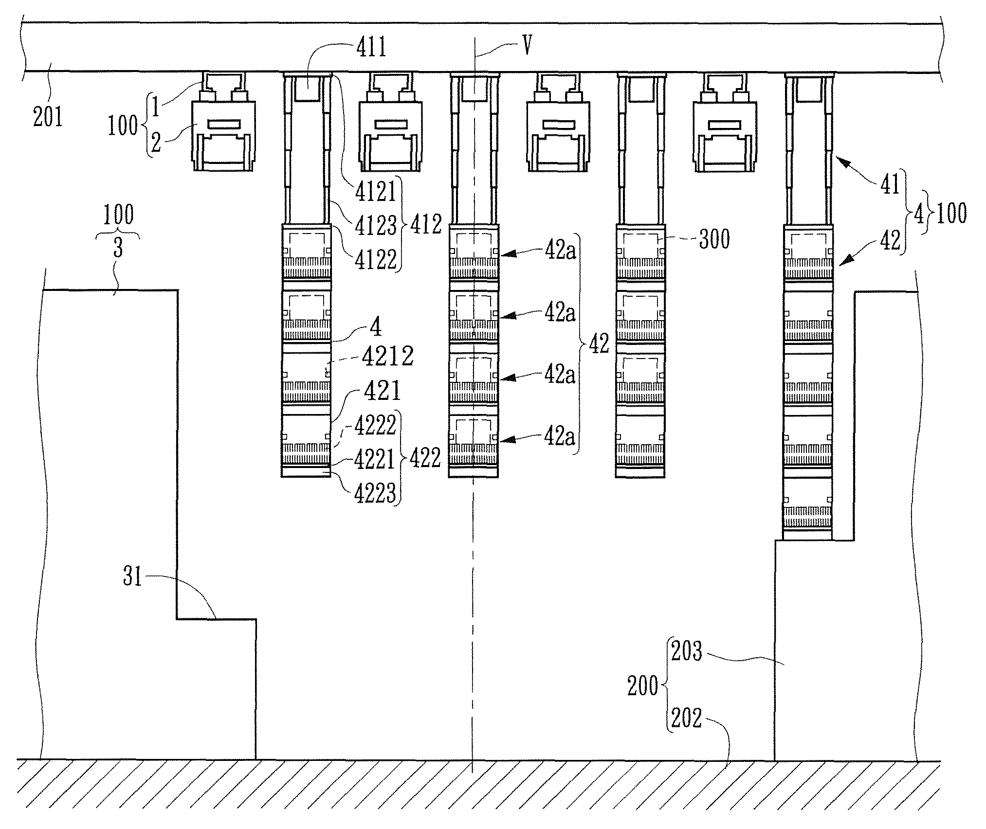
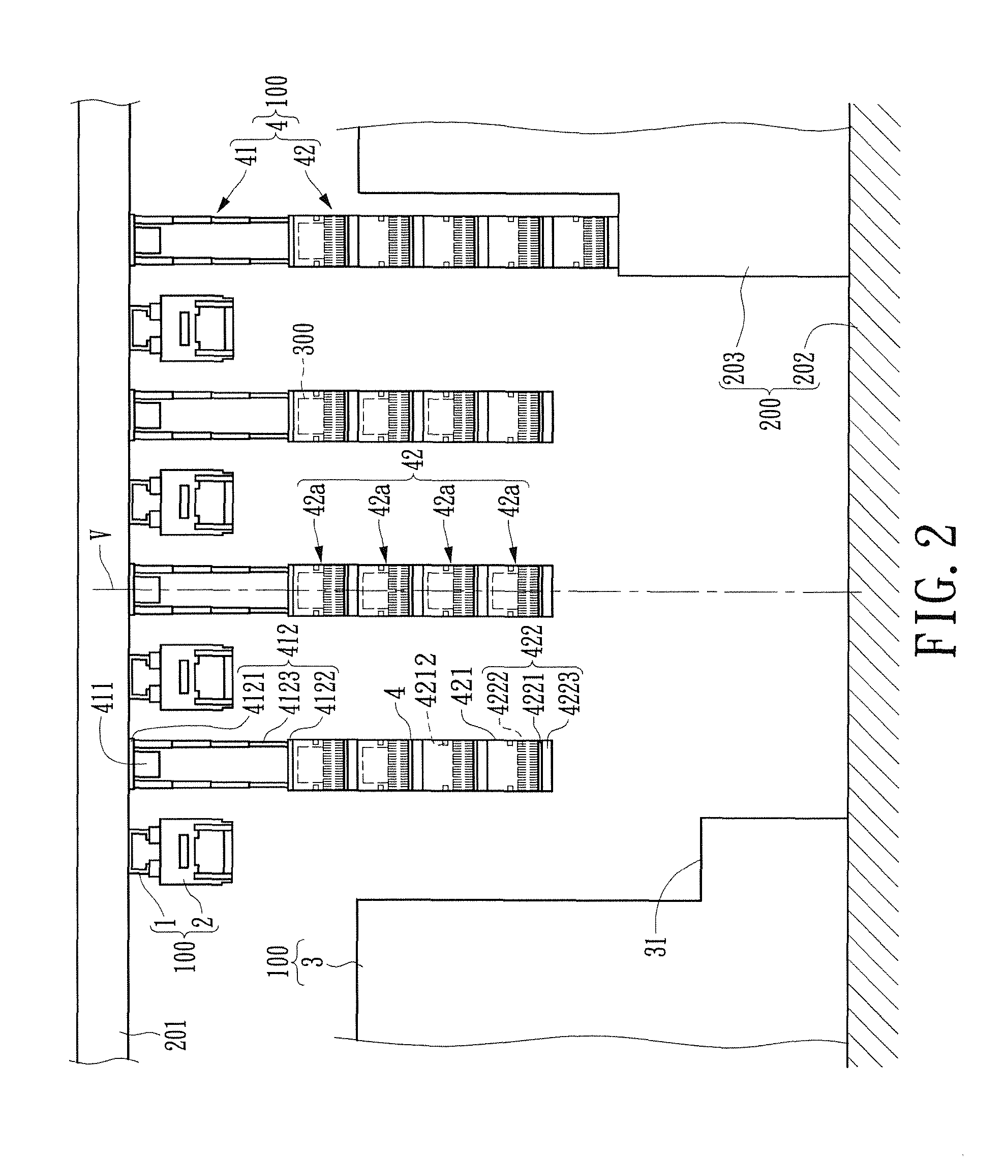
[0025]Please refer to FIGS. 2 to 6, which show an embodiment of the instant disclosure. The embodiment provides a wafer transport system 100, which is configured to be disposed in a semi-conductor factory 200 for transporting a plurality of front opening unified pods (FOUPs) 300.

[0026]Please refer to FIG. 2. The wafer transport system 100 has a plurality of overhead tracks 1, a plurality of overhead transport vehicles 2, a plurality of processing tools 3, and a plurality of overhead buffer devices 4. The following description takes one group of the overhead track 1, the overhead transport vehicle 2, the processing tool 3, and the overhead buffer devices 4, which are cooperated with each other and shown at the left portion of FIG. 2, for example, but not limited thereto.

[0027]Moreover, the movement in this embodiment is driven by an outer device (not shown). The outer device is a conventional device, so that this embodiment does not state the outer device in the following description...


PUM


Abstract

An overhead buffer device used for disposing in a semi-conductor factory includes a strut module and a plurality of buffer modules. The strut module disposed on the top wall of the factory has a horizontal beam and a plurality of overhead strut. The overhead strut is set on the horizontal beam and spaced arranged along the horizontal beam. The buffer modules are installed on the overhead strut respectively. Each buffer module has a plurality of buffers arranged in sequence and along a vertical direction. Each buffer is used for receiving one front opening unified pod (FOUP). Thus, the instant disclosure can be used for using the space of the factory efficiently. Besides, the instant disclosure also provides a wafer transport system having the overhead buffer device.

Description

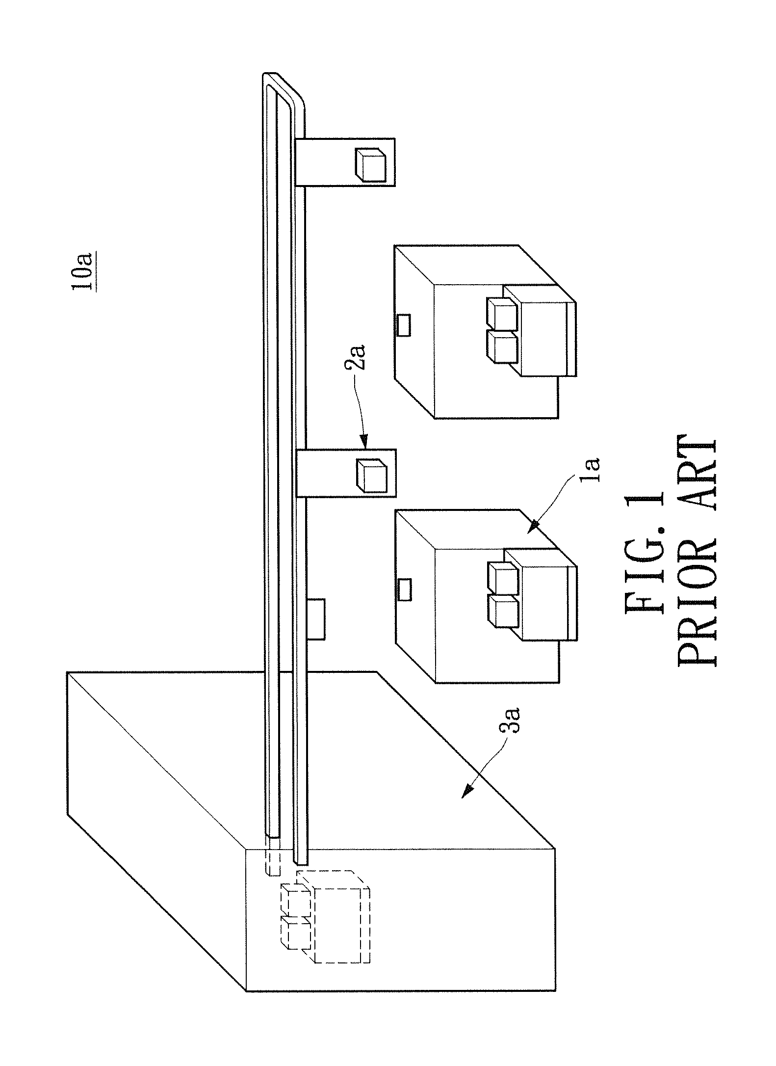
FIELD OF THE INVENTION[0001]The instant disclosure relates to a storage buffering device and a transport system; more particularly, to an overhead buffer device and a wafer transport system.DESCRIPTION OF RELATED ART[0002]Advance in technology today, the semiconductor industry has become one of the most important manufacturing industries, and the mainstream production process of the semiconductor industry develops toward the high-end process as technology development. For one thing, the norm of semiconductor fabrication has moved from 8-inch wafer gradually toward 12-inch wafer.[0003]However, the weight of 12-inch wafer is not humanly possible load, so that transportation of the 12-inch wafer must rely on the automated material handling system (AMHS). Furthermore, as shown in FIG. 1, each processing tool 1a of the wafer transport system 10a is only equipped with a buffer region 2a, which is used for receiving one front opening unified pod (FOUP). That is to say, if the buffer region...

Claims


Application Information

Patent Timeline
Patent Type & Authority Patents(United States)
IPC IPC(8): H01L21/677B61B10/02B65G49/07B61B3/02
CPCH01L21/67769H01L21/67733B61B3/02B61B10/022B65G49/07H01L21/67775
Inventor FENG, HANG-HAOCHANG, SHENG-JUNG
Owner MICRON TECH INC
Learn More