
Multi-source active injection load pull system and method

a technology of active injection and load pull, which is applied in the direction of resistance/reactance/impedence, instruments, measurement devices, etc., can solve the problems of large impedance mismatch between output and output, reduce the tuning range, and reduce the complexity and especially the cost of the test setup

Active Publication Date: 2015-12-15
TSIRONIS CHRISTOS
View PDF5 Cites 10 Cited by
  • Summary
  • Abstract
  • Description
  • Claims
  • Application Information

AI Technical Summary

Benefits of technology

The patent text describes a method for testing and characterizing RF and microwave transistors on wafer. This method allows for testing devices without the need for packaging them in test fixtures, but it does have some limitations. One limitation is that the tuning range of the devices is reduced compared to off-wafer testing. To compensate for this, an active load pull system has been introduced, which uses a harmonic receiver and a power amplifier to create a virtual reflection factor that matches the impedance of the device under test. This allows for better matching of the device's internal impedance despite any insertion losses. The technical effect of this invention is to improve the accuracy and reliability of on-wafer testing for RF and microwave transistors.

Problems solved by technology

On-wafer testing is also the exclusive testing method in millimeterwave frequencies, since device packaging is extremely difficult and the parasitic elements associated with the package (inductance of wire bonds and fringe capacitors of package housings) would falsify the measured data to the point of uselessness.
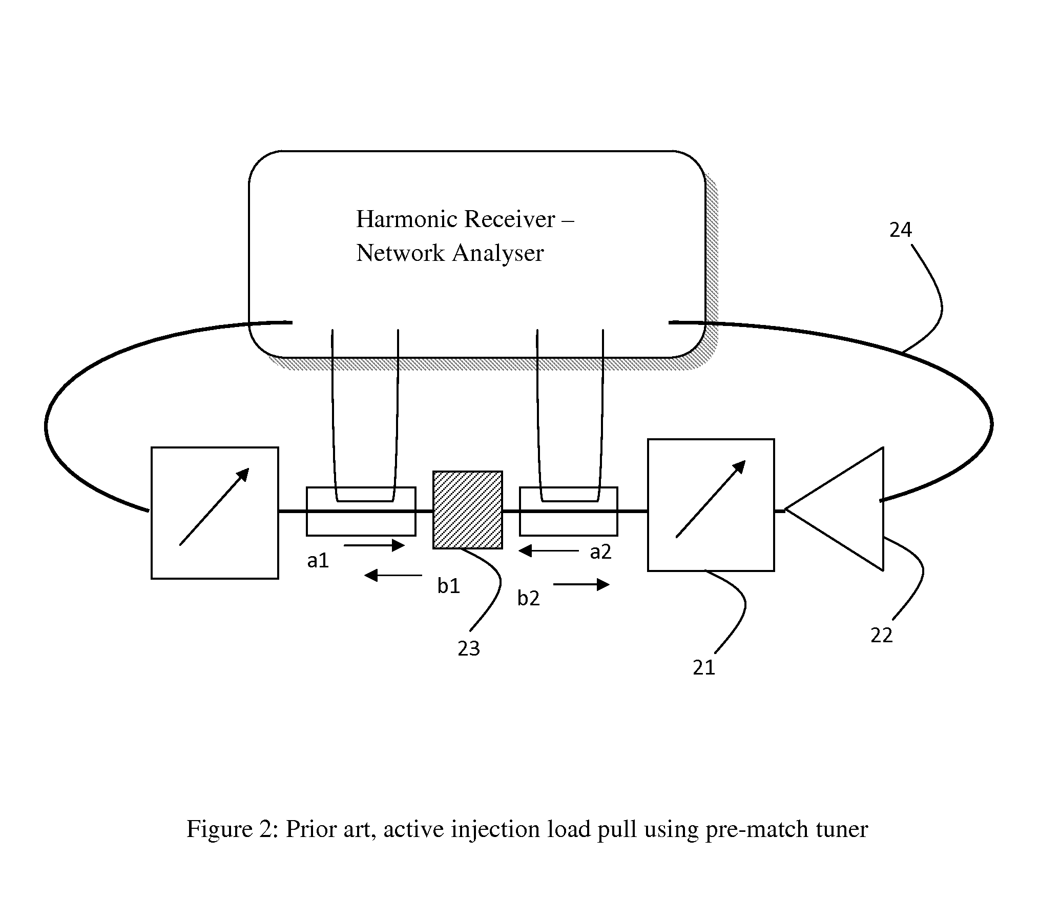
However, on-wafer testing implies reduced tuning range.
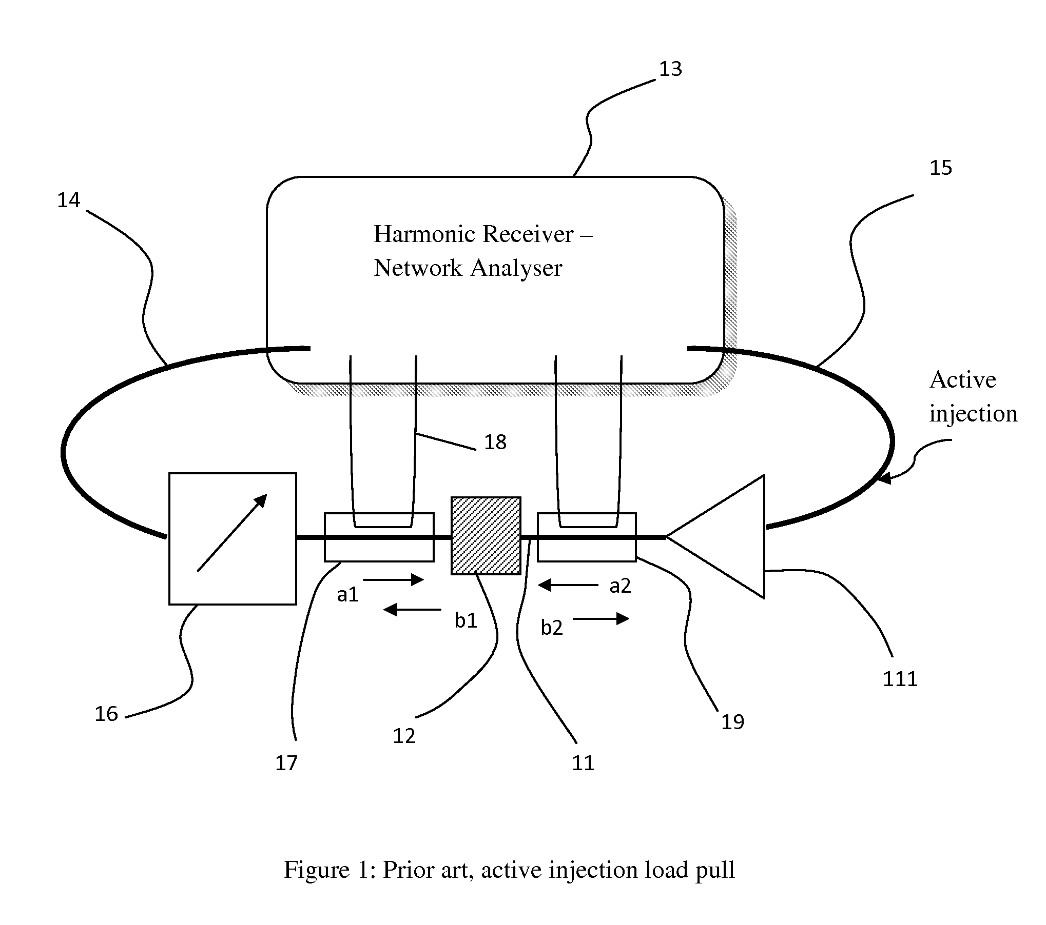
The actual problem with this configuration is that there exist, typically, a large impedance mismatch between the output of the power amplifier (111) and the output of the DUT (11).
This reduces significantly the complexity and especially the cost of the test setup, since power amplifiers can be expensive.
The problem with the setup of FIG. 3 is that a wideband impedance tuner (33) is used.
Because harmonic frequencies are high, associated power amplifiers are very expensive [3].
This is all in addition to any unavoidable connection and adapter losses.

Method used


Image

  • Multi-source active injection load pull system and method
  • Multi-source active injection load pull system and method
  • Multi-source active injection load pull system and method

Examples


Embodiment Construction

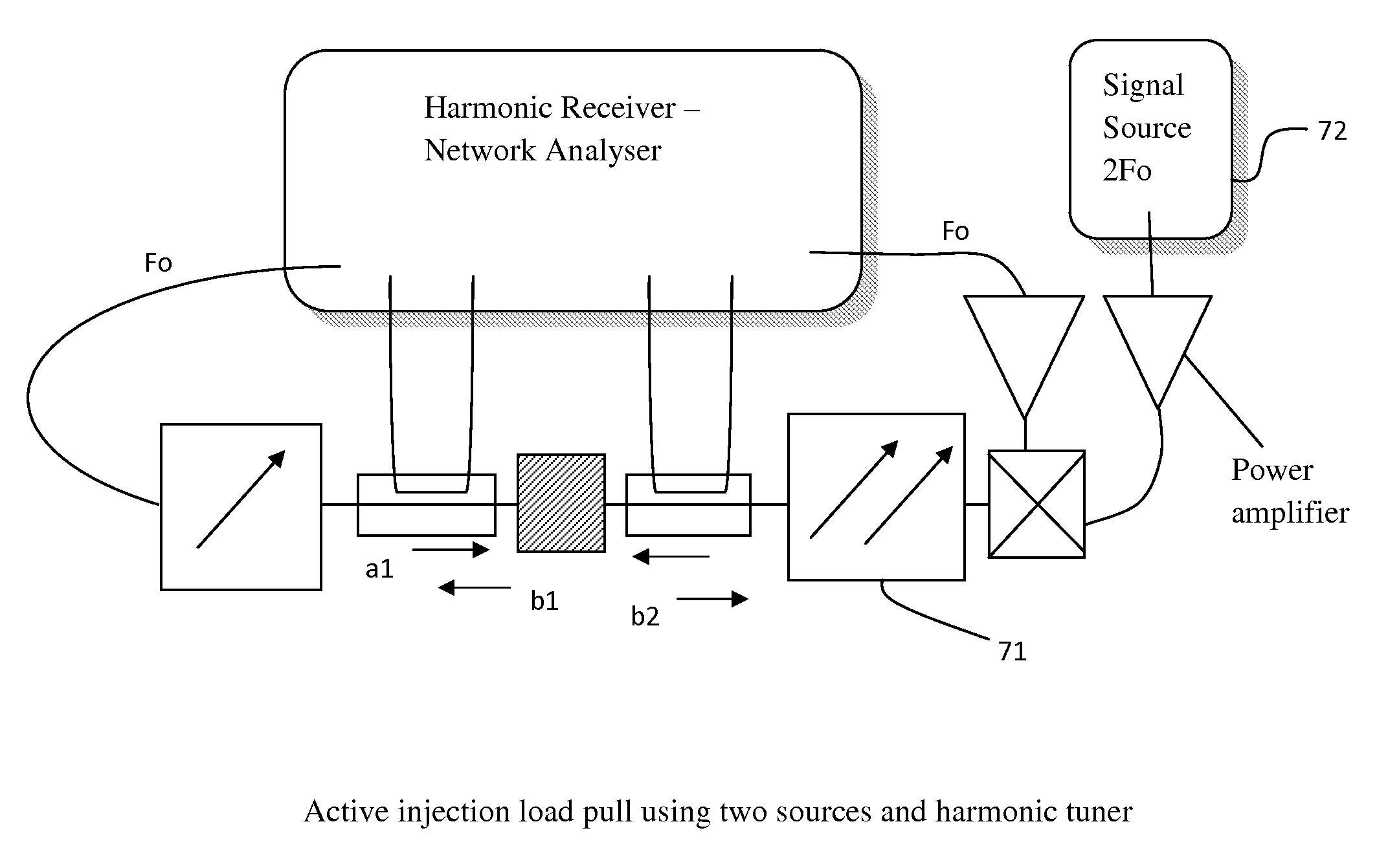
[0029]The proposed solution serving to reduce the power requirement of the injection amplifiers in open loop harmonic injection load pull test systems is shown in FIGS. 7 to 9 [6]. Instead of using single carriage wideband tuners (33) another type of impedance tuners are employed, the multi-carriage harmonic tuners [2] (71, 81). Harmonic tuners [2] operate in such a way as to be able to generate arbitrary impedances Z(Fi) at different frequencies, including harmonic frequencies Fi (Fo, 2Fo, 3Fo . . . ), independently on each-other. The harmonic tuners in the setups of FIGS. 7 to 9 allow the pre-matching of the DUT to the load at each harmonic frequency independently and as close as possible to the conjugate complex internal impedance (optimum matching impedance) of said DUT at the specific frequency. This allows operating at point (51) in the diagram of FIG. 5, i.e. with minimum or zero requirement of injected power at the fundamental and any harmonic frequency. It has to be emphasi...


PUM


Abstract

A harmonic load pull system uses a number of synchronized signal sources to inject harmonic power into the output of a power transistor. The mismatch between the signal sources and the transistor internal impedance is reduced by using multi-harmonic tuners, which pre-match the impedance of the signal sources to the internal impedance of the transistor at each harmonic frequency independently. Actual tuning is electronic by changing the amplitude and phase of the injected signals. The transmitted and reflected waves are measured and optimized through bi-directional couplers connected between the transistor and the tuner and a wideband harmonic receiver.

Description

PRIORITY CLAIM[0001]This application claims priority on provisional application 61 / 660,158 filed on Jun. 15, 2012.CROSS-REFERENCE TO RELATED ARTICLES[0002][1]“ALPS-308, Active Load Pull System for PCN Applications”, Product Note 33, Focus Microwaves Inc., April 1996.[0003][2]“MPT a universal Multi-Purpose Tuner”, Product Note 79, Focus Microwaves Inc., October 2004.[0004][3] POWER AMPLIFIERS: http: / / www.amlj.com / display2.php3?FreqRange=&freqband=ganamps&location=cam[0005][4] Z. ABOUSH et al., “High power active harmonic load-pull system for characterization of high power 100 Watt transistor”, 35th EuMC, October 2005, Paris.[0006][5]“Cascading Tuners For High-VSWR And Harmonic Load Pull”, Maury Microwave Application Note 5C-081, January 2009.[0007][6]“Hybrid Active and Harmonic Tuning”, Application Note 62, Focus Microwaves Inc., December 2011.[0008][7] U.S. Pat. No. 5,276,411, High power solid state programmable load.BACKGROUND OF THE INVENTIONPrior Art[0009]RF and Microwave transis...

Claims


Application Information

Patent Timeline
Patent Type & Authority Patents(United States)
IPC IPC(8): G01R31/26G01R1/04
CPCG01R31/2621G01R1/0491G01R27/28
Inventor TSIRONIS, CHRISTOS
Owner TSIRONIS CHRISTOS
Learn More