Process for recovering olefins in polyolefin plants

a polyolefin plant and olefin technology, applied in the direction of separation process, organic chemistry, dispersed particle separation, etc., can solve the problems of olefin loss, small portion of olefin feedstock loss through raw material purification, and annual loss of $1 million to $3 million for a typical polyolefin plan

Active Publication Date: 2015-12-22
MEMBRANE TECH & RES
View PDF8 Cites 11 Cited by
  • Summary
  • Abstract
  • Description
  • Claims
  • Application Information

AI Technical Summary

Benefits of technology

[0022]The condensation step usually involves chilling and compression. Compressing the has raises the dewpoint temperature, so a combination of compression and chilling is generally preferred. Occasionally, however, the purge process, or other upstream treatments, may be such that the purge stream is already at high pressure. In this case, chilling alone may suffice to induce condensation, and the compression step may be dispensed with.

Problems solved by technology

During polyolefin production, a small portion of the olefin feedstock is lost through raw material purification, chemical reaction, and product purification and finishing.
In particular, paraffin that enters with the olefin feedstock must be removed to prevent its build up in the reactor loop, and olefin is lost when this paraffin is purged from the loop.
This results in an annual loss of $1 million to $3 million per year for a typical polyolefin plant.
In the past, this vent gas was sent for flaring, resulting in a waste of unreacted olefin.
However, little is taught on recovering unreacted olefins from the condensed liquid stream.

Method used


Image

  • Process for recovering olefins in polyolefin plants
  • Process for recovering olefins in polyolefin plants
  • Process for recovering olefins in polyolefin plants

Examples


example 1

Treatment of the Uncondensed Gas Stream Not in Accordance with the Invention

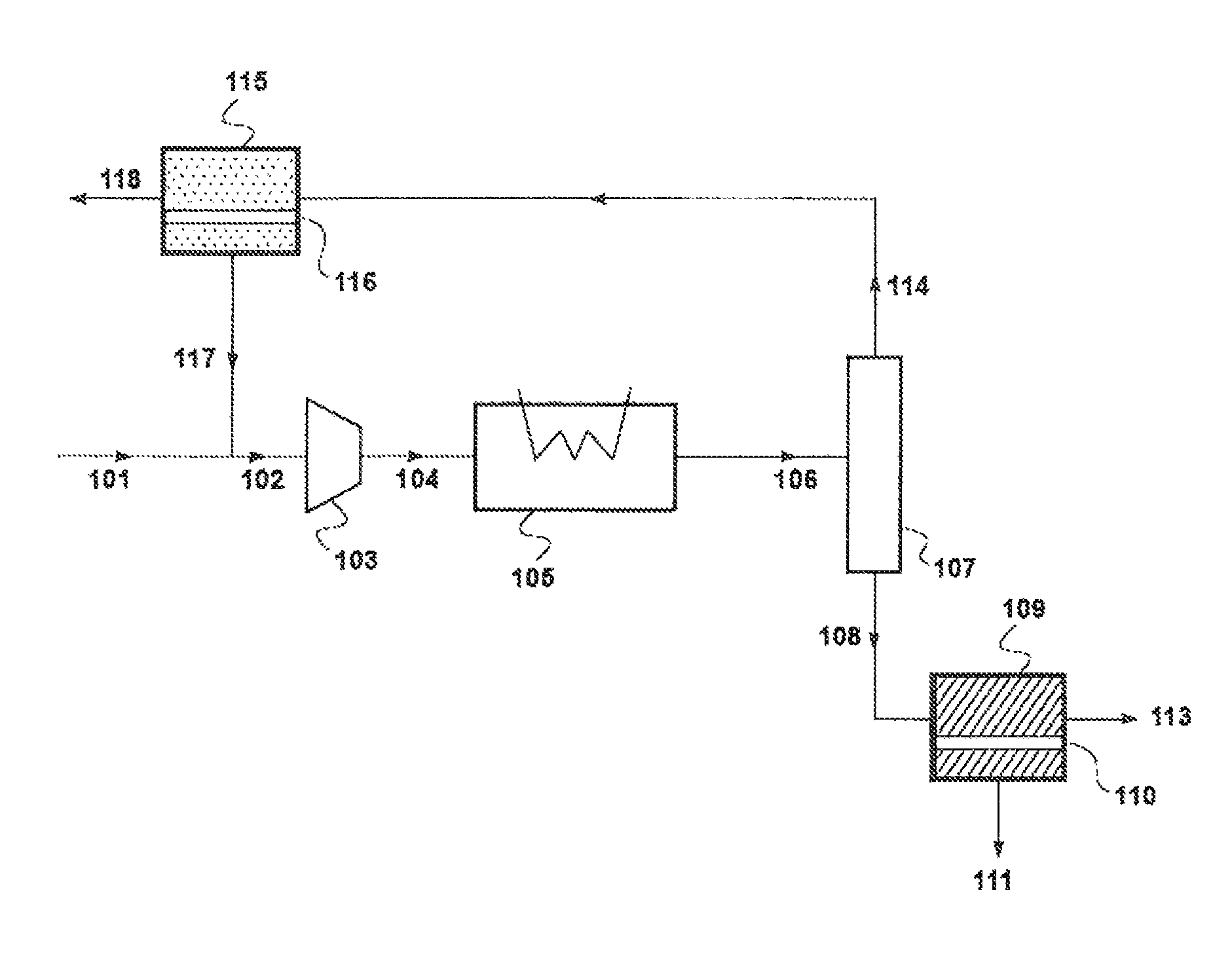
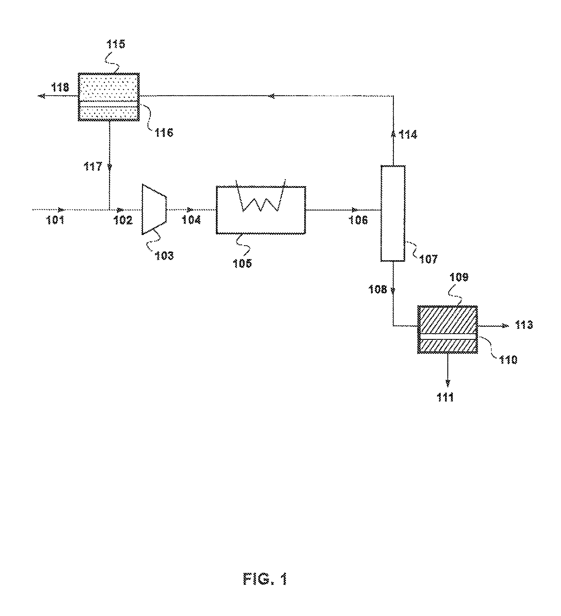
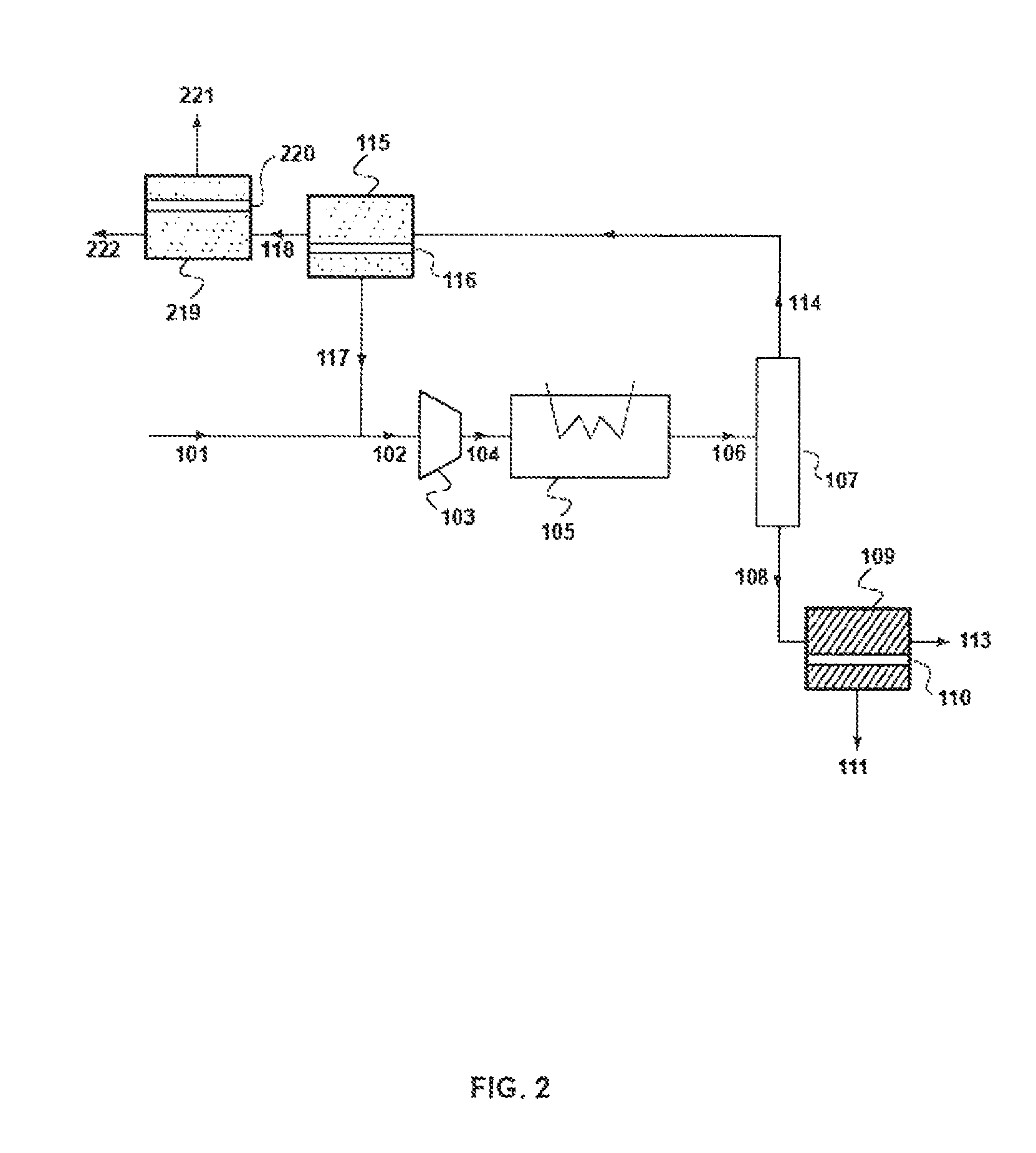
[0159]For comparison with the following examples, a calculation was performed in a process where only the uncondensed gas stream 114 from separator 107 was treated. In other words, stream 108 was withdrawn from the separator and was not further treated. The treatment included using two membrane separation steps, similar to steps 115 and 219 in FIG. 2. Likewise, the streams are labeled to correspond with the treatment process of the uncondensed gas stream represented in FIG. 2.

[0160]For the calculation, the purge stream was assumed to have a flow rate of 1,139 kg / hour and contain propylene, propane, and nitrogen. It as also assumed that the molar compositions were approximately as follows:[0161]Nitrogen: 76%[0162]Propylene: 21%[0163]Propane: 3%

[0164]It was further assumed that the purge stream was compressed to 24 bara in compression step 103, then cooled to −20° C. in condensation step 105.

[0165]The calculat...

example 2

Purge Stream Recovery Process in Accordance with the Invention of FIG. 3

[0169]A calculation was performed to model the performance of the process of FIG. 3 in treating a purge stream from a purge bin offgas of a polymerization process. The membrane separation of the liquid condensate occurred under pervaporation conditions.

[0170]The results of the calculations are shown in Table 2.

[0171]

TABLE 2Stream101108a108b111113316317114117118221222Mass1,139805805325480434372,2701,500771135636flow(kg / h)Temp70−204040403829−2028222221(° C.)Pressure1232312221123123323(bara)Component (mol %)Nitrogen75.93.83.80.56.030.03.483.261.299.097.099.5Propylene20.876.576.593.864.97.171.113.830.30.82.50.4Propane3.319.819.85.829.162.925.53.18.50.20.60.1Mass flow (kg / h)Nitrogen77020201199101,737977760129 631Propylene3166186183043133310432424954Propane53167167201483111710199211

[0172]Using polymeric membranes to treat the uncondensed gas stream and inorganic membranes to treat the condensate, the process achieves ...

example 3

Purge Stream Recovery Process in Accordance with the Invention of FIG. 5

[0173]A calculation was performed to model the performance of the process of FIG. 5 in treating a purge stream from a polyolefin manufacturing process. The results of the calculations are shown in Table 3.

[0174]

TABLE 3Stream101108509512513114117118221222Mass flow1,139367367300682,275 1,503772135637((kg / h)Temp70−20333129−2028222221(° C.)Pressure12331323123323(barn)Component (mol %)Nitrogen 75.93.73.70.816.283.073.799.096.999.5Propylene 20.883.183.192.941.015.023.10.82.70.4Propane3.313.213.26.242.82.13.20.10.40.1Mass flow (kg / h)Nitrogen 77099281,737976761129632Propylene 317307 307278294704611054Propane52515120316866111

[0175]Using polymeric membranes to treat the uncondensed gas stream and an inorganic membrane to treat the condensate, the process achieves 88% recovery of olefin. The ratio of propylene to propane in purge stream 513 is reduced to less than 1:1.


PUM

PropertyMeasurementUnit
temperatureaaaaaaaaaa
mol %aaaaaaaaaa

Abstract

A process for recovering unreacted olefin in a polyolefin manufacturing process comprising the treatment of a purge bin vent gas. The process involves cooling and condensing the vent gas (purge stream), which contains at least an olefin, a paraffin, and hydrogen, to produce a liquid condensate and an uncondensed (residual) gas stream. Both streams are then passed through membrane separation steps. The membrane separation of the uncondensed gas stream results in a residue stream containing mostly nitrogen and/or paraffin and a permeate stream enriched in either C2+ hydrocarbons or olefin, depending on the type of separation. The permeate from this step is recirculated within the process prior to the condensation step. The membrane separation of the condensate results in a residue stream containing paraffin and a permeate stream enriched in olefin, which may be recycled to the polymerization reactor.

Description

CROSS-REFERENCE TO RELATED APPLICATIONS[0001]This application is a continuation-in-part of U.S. application Ser. No. 14 / 486,382 filed Sep. 15, 2014, now U.S. Pat. No. 9,073,808, the disclosure of which is hereby incorporated herein by reference in its entirety.FIELD OF THE INVENTION[0002]The invention relates to a process for recovering olefins in a polyolefin manufacturing process. More specifically, the invention relates to treating a purge bin vent gas stream using gas separation membranes for recovering unreacted olefin and selectively purging paraffin from the polymerization process.BACKGROUND OF THE INVENTION[0003]Polyethylene (PE) and polypropylene (PP) are two of the most demanded polymers in the world. Together, these polymers make up half of the volume of plastic produced worldwide.[0004]During polyolefin production, a small portion of the olefin feedstock is lost through raw material purification, chemical reaction, and product purification and finishing. In particular, p...

Claims


Application Information

Patent Timeline
Patent Type & Authority Patents(United States)
IPC IPC(8): C07C7/144C07C7/00C07C7/09
CPCC07C7/005C07C7/144C07C7/09B01D53/002B01D53/225B01D53/229B01D61/362B01D61/58B01D2256/24B01D2257/108B01D2257/702C01B3/501C01B2203/048C07C11/04C07C11/06
Inventor SU, PAUL
Owner MEMBRANE TECH & RES
Why Eureka
Try Eureka