Vacuum pump

a vacuum pump and vacuum technology, applied in the field of vacuum pumps, can solve the problems of increasing the number of parts, increasing the number of assembly man-hours, and easy breakage of the portion, and achieve the effect of reducing costs and high loads

Active Publication Date: 2015-12-22
EDWARDS JAPAN
View PDF10 Cites 3 Cited by
  • Summary
  • Abstract
  • Description
  • Claims
  • Application Information

AI Technical Summary

Benefits of technology

[0016]Therefore, it is an object of the present invention to solve the technical problem to be solved and that arises herein, namely the need for providing a composite-type vacuum pump that uses a cylindrical rotor obtained through shaping of a fiber-reinforced plastic material, such that the composite-type vacuum pump is strong enough to withstand high loads and is amenable to reduction in cost.
[0023]In the invention set forth in the first aspect, an upper end face of the cylindrical rotor protrudes above a contact portion of the cylindrical rotor and the second rotor; as a result, it becomes possible to prevent a high load from acting on the upper end face of a cylinder that has a lower material strength than other portions.
[0024]In the invention set forth in the second aspect, a joint portion is formed to an L-shape that protrudes below an annular-brim portion, and an upper end face of a cylindrical rotor is escaped below the annular-brim portion. Loads can be eased thereby through deflection of the protruding section of the joint portion. As a result, it becomes possible to prevent a high load from acting on the upper end face of a cylinder that has a lower material strength than other portions.
[0025]In the invention set forth in the third aspect, a joint portion is formed to an L-shape that protrudes below an annular-brim portion, and an upper end face of a cylindrical rotor is escaped below the annular-brim portion. Loads can be eased thereby through deflection of the protruding section of the joint portion. As a result, it becomes possible to prevent a high load from acting on the upper end face of a cylinder that has a lower material strength than other portions.
[0026]In the invention set forth in the fourth aspect, a joint portion is formed to an L-shape that protrudes below an annular-brim portion, a small-diameter section is provided at an upper portion of the joint portion, and a contact portion of a cylindrical rotor and a second rotor is escaped under the annular-brim portion. Loads can be eased thereby through deflection of the protruding section of the joint portion. Also, the upper end face of the cylindrical rotor protrudes above the contact portion. As a result, it becomes possible to prevent a high load from acting on the upper end face of a cylinder that has a lower material strength than other portions.

Problems solved by technology

This raised the concern of easy breakage of that portion when acted upon by a load.
In an FRP structure, however, there is hardly any deflection in the vicinity of the end face, at which strength is weakest, and hence hardly any load-relieving effect is afforded.
However, the structure disclosed in Japanese Patent No. 3098139, wherein the rotor of the turbo-molecular pump section and the cylindrical rotor of the thread groove pump section were joined to each other by way of a support plate of an FRP material, was problematic on account of the increased number of parts and greater assembly man-hours that such a structure involved.
Moreover, assembly was difficult to achieve with good precision, and the clearance with respect to a fixed section had to be made wider than in a conventional instance, in order to prevent contact with the fixed section.
This entailed lower evacuation performance, which was likewise problematic.
In the structure disclosed in Japanese Patent Application Publication No. 2004-278512, i.e. a structure wherein the winding angle of fibers of an FRP material, and shaping shapes and conditions, such as resin content, were variously designed, the shape of the FRP material was a complex one, which was problematic in terms of poorer productivity and higher costs that this entailed.

Method used


Image

  • Vacuum pump
  • Vacuum pump
  • Vacuum pump

Examples


Embodiment Construction

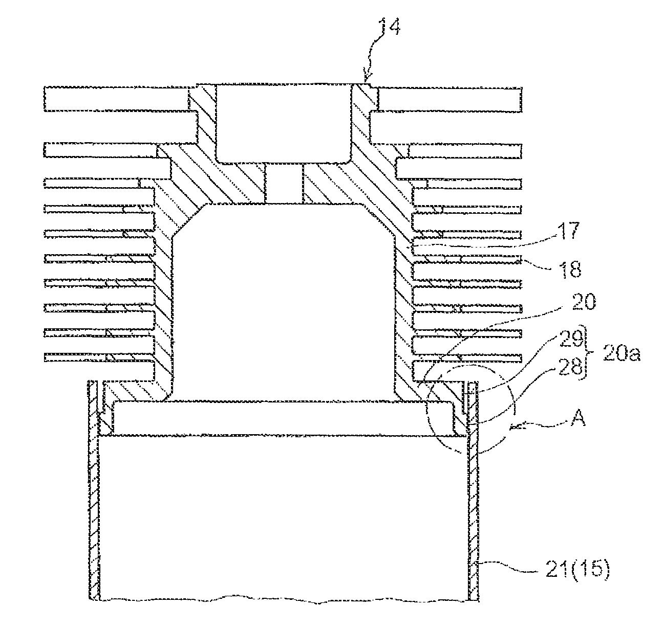
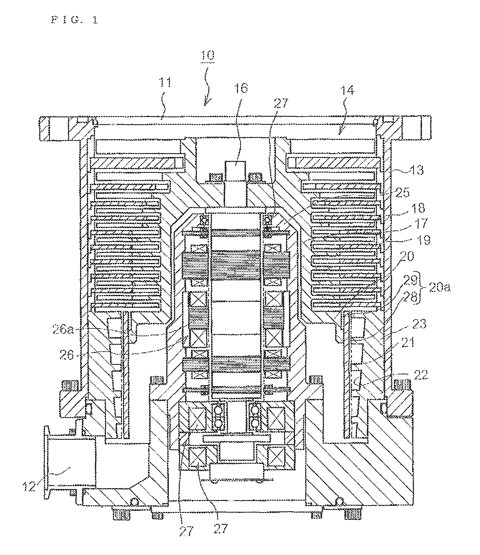
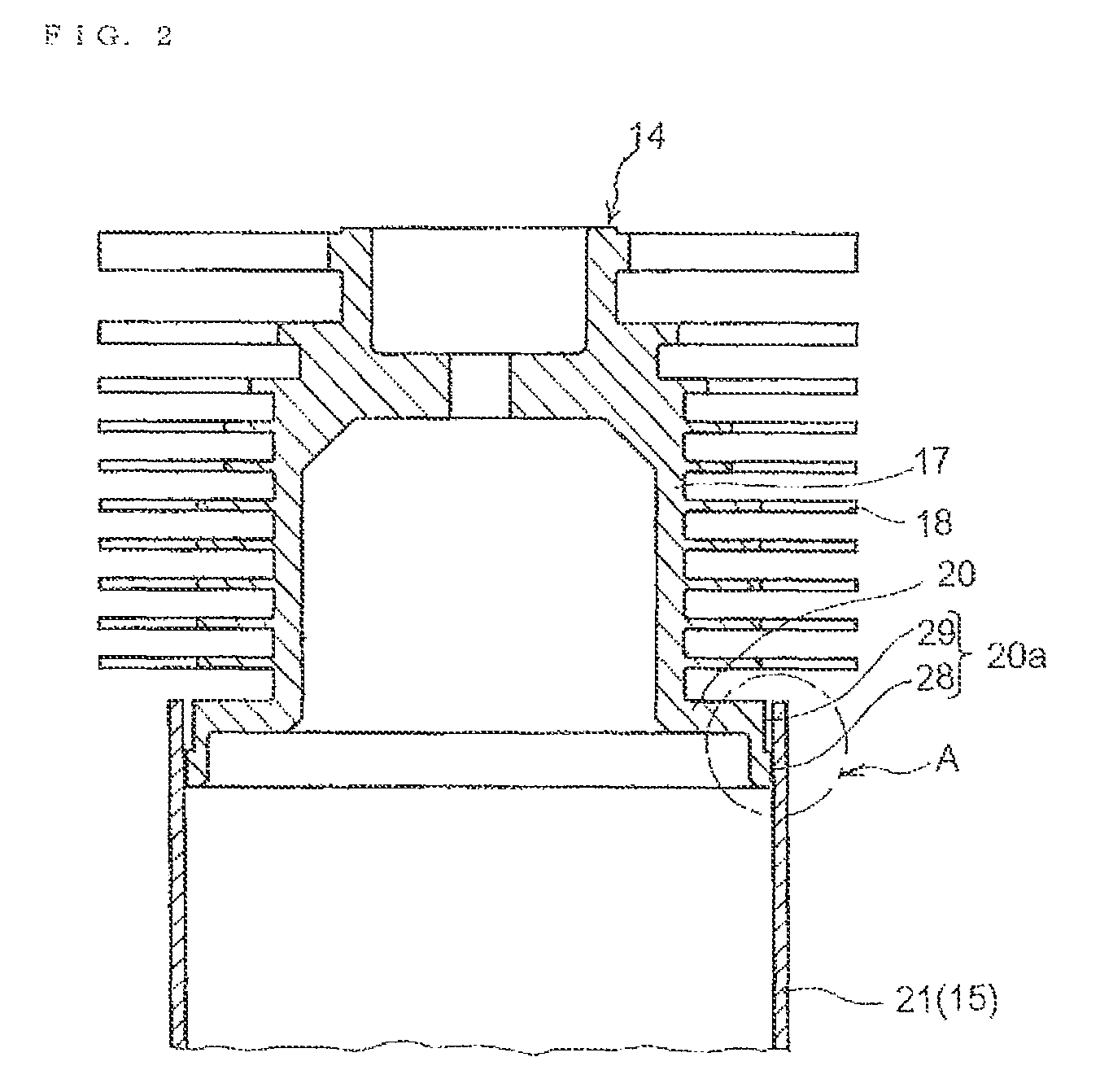
[0042]In the present invention, the goal of providing a composite-type vacuum pump that uses a cylindrical rotor obtained through shaping of a fiber-reinforced plastic material, such that the composite-type vacuum pump is strong enough to withstand high loads, and is amenable to reduction in cost, was attained by providing a vacuum pump that comprises a cylindrical rotor that has at least a thread groove pump section or a Goethe pump section, and a rotor that has a turbo-molecular pump section or a vortex pump section or the like, the vacuum pump being configured through joining of part of a side surface of the cylindrical rotor to a joint portion that is provided at an annular-brim portion formed in the rotor, wherein the joint portion is formed, integrally with the annular-brim portion, to an L-shape.

[0043]Embodiments

[0044]Preferred embodiments of the composite-type vacuum pump of the present invention are explained below with reference to accompanying drawings. FIG. 1 and FIG. 2 ...


PUM


Abstract

Disclosed is a low-cost composite-type vacuum pump having a strength capable of withstanding high loads and using a cylindrical rotor formed from a fiber-reinforced plastic material. Having a turbo-molecular pump section (14) and a thread groove pump section (15), the composite vacuum pump is formed by press-fitting a joint portion (20a) of a rotor (17) of the turbo-molecular pump section (14) into the upper end section of a cylindrical rotor (21) formed from the fiber-reinforced plastic material of the thread groove pump section (15). The joint portion (20a) of the rotor (17) is formed on the lower end side of the rotor (17) integrally with said rotor (17) and in the shape of a cylinder with an L shaped cross section, and is provided with: a contact portion (28) having an outer diameter enable press-fitting into the inner peripheral face of the cylindrical rotor (21); and a small-diameter section (29) positioned above said contact portion (28) and, having an outer diameter smaller than the inner diameter of the aforementioned cylindrical rotor (21), capable of being placed inside the cylindrical rotor (21) away from the inner peripheral face of the cylinder rotor (21).

Description

BACKGROUND OF THE INVENTION[0001]1. Field of the Invention[0002]The present invention relates to a vacuum pump, and more particularly to a vacuum pump that can be used in a pressure range from low vacuum to high vacuum and ultra-high vacuum, in an industrial vacuum system that is used in semiconductor manufacturing, high-energy physics and the like.[0003]2. Description of the Related Art[0004]In the present description an example will be explained of a composite-type vacuum pump that is provided with a turbo-molecular pump section and a thread groove pump section. Conventional composite-type vacuum pumps of this type have a structure wherein a turbo-molecular pump section 104 and a cylindrical thread groove pump section 105 are sequentially disposed inside a chassis 103, having an intake port 101 and a discharge port 102, from the intake port 101 side, as illustrated in the vertical cross-sectional diagram of a composite-type vacuum pump in a conventional embodiment illustrated in F...

Claims


Application Information

Patent Timeline
Patent Type & Authority Patents(United States)
IPC IPC(8): F04D19/04F04D29/64
CPCF04D19/042F04D29/644F04D19/046F04D19/044F04D19/04F04D29/02F04D25/16
Inventor KABASAWA, TAKASHI
Owner EDWARDS JAPAN
Why Eureka
Try Eureka