Modified fixed-point algorithm for implementing infrared sensor radiation equation

a technology of infrared sensor and radiation equation, which is applied in the field of infrared sensors, can solve the problems of large additional chip area, and large amount of programming code, and achieve the effect of low cost ir-to-object, adequate accuracy, and fast and accurate measurement of object temperatur

Active Publication Date: 2015-12-29
TEXAS INSTR INC
View PDF4 Cites 4 Cited by
  • Summary
  • Abstract
  • Description
  • Claims
  • Application Information

AI Technical Summary

Benefits of technology

[0013]It is another object of the invention to provide a fast, low-cost IR-to-object fixed-point temperature conversion algorithm which provides adequate accuracy of the measured object temperature for many applications.
[0014]It is another object of the invention to provide a low-cost integrated circuit IR-to-object temperature conversion algorithm which provides adequate accuracy and very fast conversion of the power of infrared radiation to object temperature without substantially increasing the amount of required integrated circuit chip area.

Problems solved by technology

However, if the conversion algorithm needs to be implemented in an integrated circuit, that approach would require a great deal of additional chip area and therefore would substantially increase its cost.
However, this approach results in much slower execution of the conversion algorithm and a large amount of programming code, which requires a large amount of memory.
However, a hardware implementation of a floating point math engine is costly in terms of die area, die cost, power consumption, and engineering design time, and may not be an option for a very low cost infrared sensor having a small die or chip size.
Although floating point emulation has the advantages of providing very precise results and making it easy to modify the IR-to-temperature conversion algorithm if necessary, the amount of programming code is relatively large and the algorithm execution times are relatively slow.
This traditional implementation is not suitable for a typical IR conversion equation algorithm because of the needed range and accuracy.

Method used


Image

  • Modified fixed-point algorithm for implementing infrared sensor radiation equation
  • Modified fixed-point algorithm for implementing infrared sensor radiation equation
  • Modified fixed-point algorithm for implementing infrared sensor radiation equation

Examples


Embodiment Construction

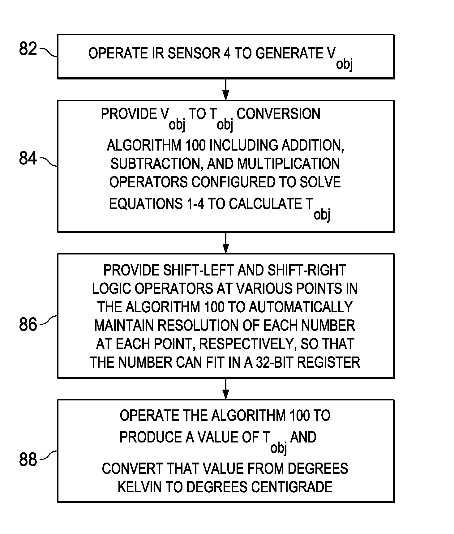
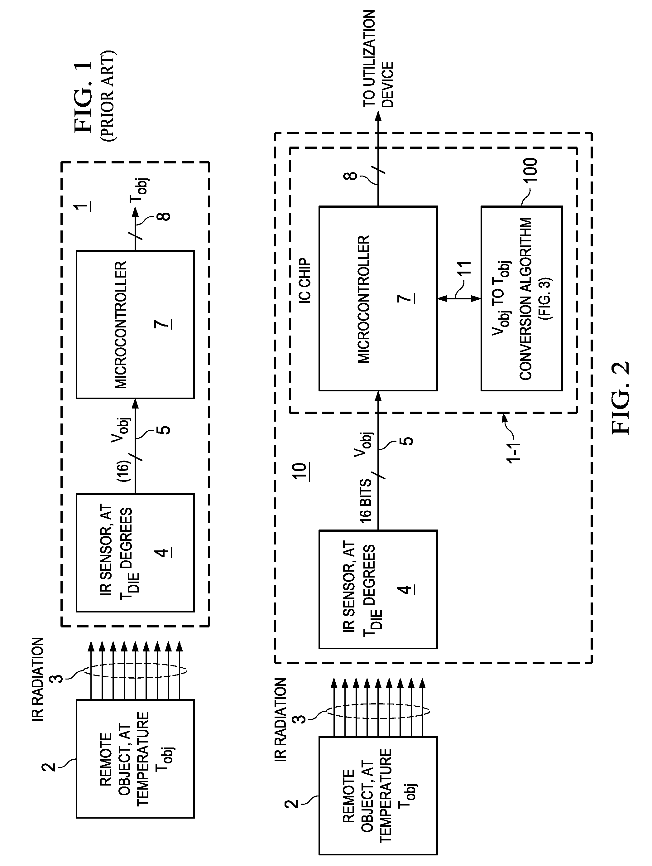
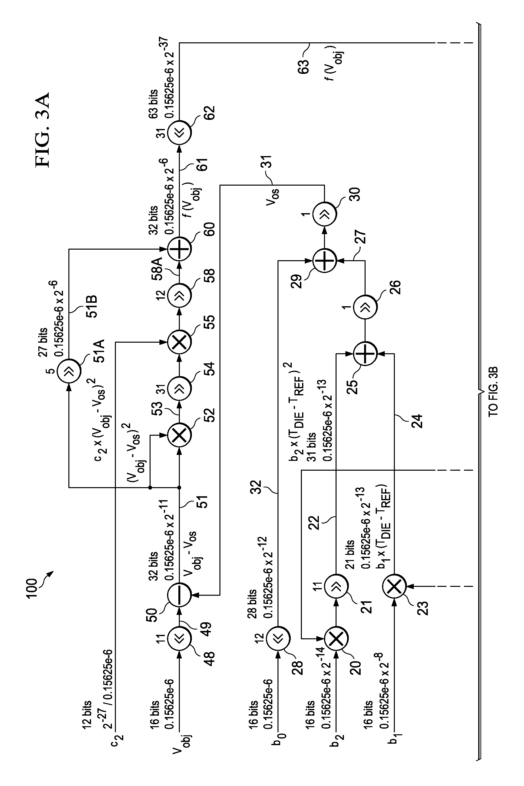
[0036]A contactless infrared (IR) sensor integrated circuit includes an IR sensor and a microcontroller which operates to convert a voltage that represents impinging IR radiation power to a digital word or number that represents the temperature of a remote object emitting the IR radiation. (The term “remote object” as used herein simply means that the IR sensor does not physically contact the surface of the object emitting the IR radiation.) The microcontroller executes a “virtual resolution” IR conversion algorithm that is executed by means of hard-wired integrated circuit logic circuitry, such as logic circuitry in a microcontroller, which precisely corresponds to the conversion algorithm and maintains “virtual resolution” of digital values expressed in scientific notation (integer value multiplied by a base number raised to an exponential power) without additional circuitry or software for keeping track of the exponents. The implementation of the conversion algorithm is optimized...


PUM


Abstract

A system including an integrated circuit chip also includes a microcontroller in the chip and an algorithm for execution by the microcontroller. The algorithm includes addition, subtraction, and multiplication operators (e.g. 25,15,20) and shift-left and shift-right operators (e.g., 48,21) configured for solving particular equations (Eqns. 1-4). Input numbers are within particular ranges to allow the shift operators to shift binary bits so each number so it fits within a register of a particular width. An IR sensor (4) may convert IR radiation (3) to produce a voltage (Vobj) representing the temperature (Tobj) of an IR emitting object (2). The algorithm (100) operates in conjunction with the microcontroller (7) to convert the voltage (Vobj) into a value representing the temperature (Tobj) of the remote object (2) without keeping track of decimal points and resolution of the numbers.

Description

CROSS REFERENCE TO RELATED APPLICATION[0001]This application claims the benefit of prior U.S. provisional application Ser. No. 61 / 704,977 filed Sep. 24, 2012, entitled “Fixed-Point Algorithm to Implement Infrared Sensor Radiation Equation”, by Habib Sami Karaki and Ankit Khanna, and incorporated herein by reference.BACKGROUND OF THE INVENTION[0002]The present invention relates generally to infrared sensors that may be used for contactless temperature measurement of a remote object, and more particularly to an algorithm that efficiently and inexpensively converts infrared radiation received from the remote object to the temperature of the object without using a floating point microcontroller.[0003]In “Prior Art”FIG. 1, a remote object 2 which has a surface temperature Tobj emits infrared radiation (IR) 3. An IR system 1 includes a conventional IR sensor 4 which generates a digital representation Vobj of the temperature of remote object 2 on a bus 5. Vobj is provided as an input to a ...

Claims


Application Information

Patent Timeline
Patent Type & Authority Patents(United States)
IPC IPC(8): G06F17/11G06F7/483G01J5/10
CPCG06F7/483G06F17/11G01J5/10
Inventor KARAKI, HABIB SAMIKHANNA, ANKIT
Owner TEXAS INSTR INC
Why Eureka
Try Eureka