Decoding apparatus and decoding method

a decoding apparatus and data technology, applied in the direction of coding, digital signal error detection/correction, instruments, etc., can solve the problems of difficult sampling a plurality of reproduced signals at the same time in each cycle, poor quality of reproduced signals, and high so as to reduce the error rate of decoding data and increase s/n

Active Publication Date: 2016-01-26
PANASONIC INTELLECTUAL PROPERTY MANAGEMENT CO LTD
View PDF16 Cites 0 Cited by
  • Summary
  • Abstract
  • Description
  • Claims
  • Application Information

AI Technical Summary

Benefits of technology

[0013]The present invention has been created to resolve the above-described problems, and it is an object thereof to provide a decoding apparatus and a decoding method that can reduce the error rate of the decoded data and increase S / N.
[0016]In accordance with the present invention, decoding is performed a plurality of times by using reliability information on the same data block with respect to data with a high error rate prior to error correction. Therefore, the error rate of the decoded data can be reduced and S / N can be increased.

Problems solved by technology

However, in a reproduction system such as uses the aforementioned error correction technique, the quality of the reproduced signals is poor.
Therefore, it is very difficult to sample a plurality of reproduced signals at the same timing in each cycle.
However, when the quality of the reproduced signals is poor, the signals are very difficult to reproduce at the same timing, and in extreme cases, a bit slip occurs in a synchronization circuit (PLL (Phase Locked Loop) circuit).
The resultant problem is that a synchronization shift occurs in waveform sampling, and the reproduction performance is greatly degraded.
By contrast, where the synchronization shift (timing shift) occurs, as shown in FIG. 18, the averaging cannot be correctly performed by using the reproduced waveform of the first cycle and the reproduced waveform of the second cycle, and multiple reproductions degrade the error rate with respect to that obtained with a single reproduction.
Therefore, in the signal processing system, the usual synchronization processing of reproduced signals by the synchronization pattern or the like cannot be performed and signals cannot be sent to the error correcting device at a correct timing.
In the conventional devices in which a plurality of reproductions is performed, the abovementioned problem mainly occurs due to the averaging of the reproduced signals performed before the synchronization.
In a system such that uses the LDPC code, the error rate of the reproduced signals prior to error correction is high and the abovementioned problem becomes more serious.

Method used


Image

  • Decoding apparatus and decoding method
  • Decoding apparatus and decoding method
  • Decoding apparatus and decoding method

Examples


embodiment 1

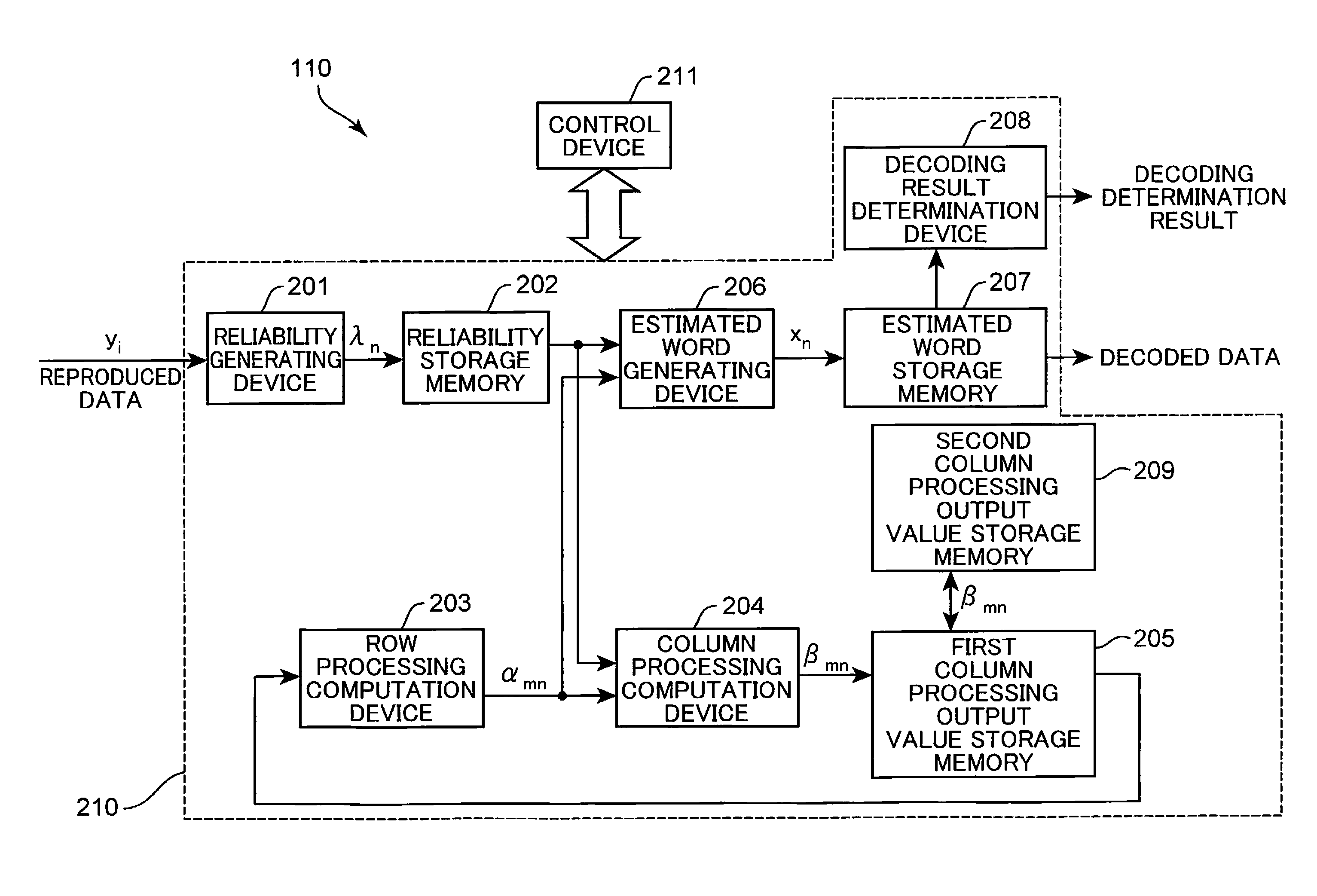
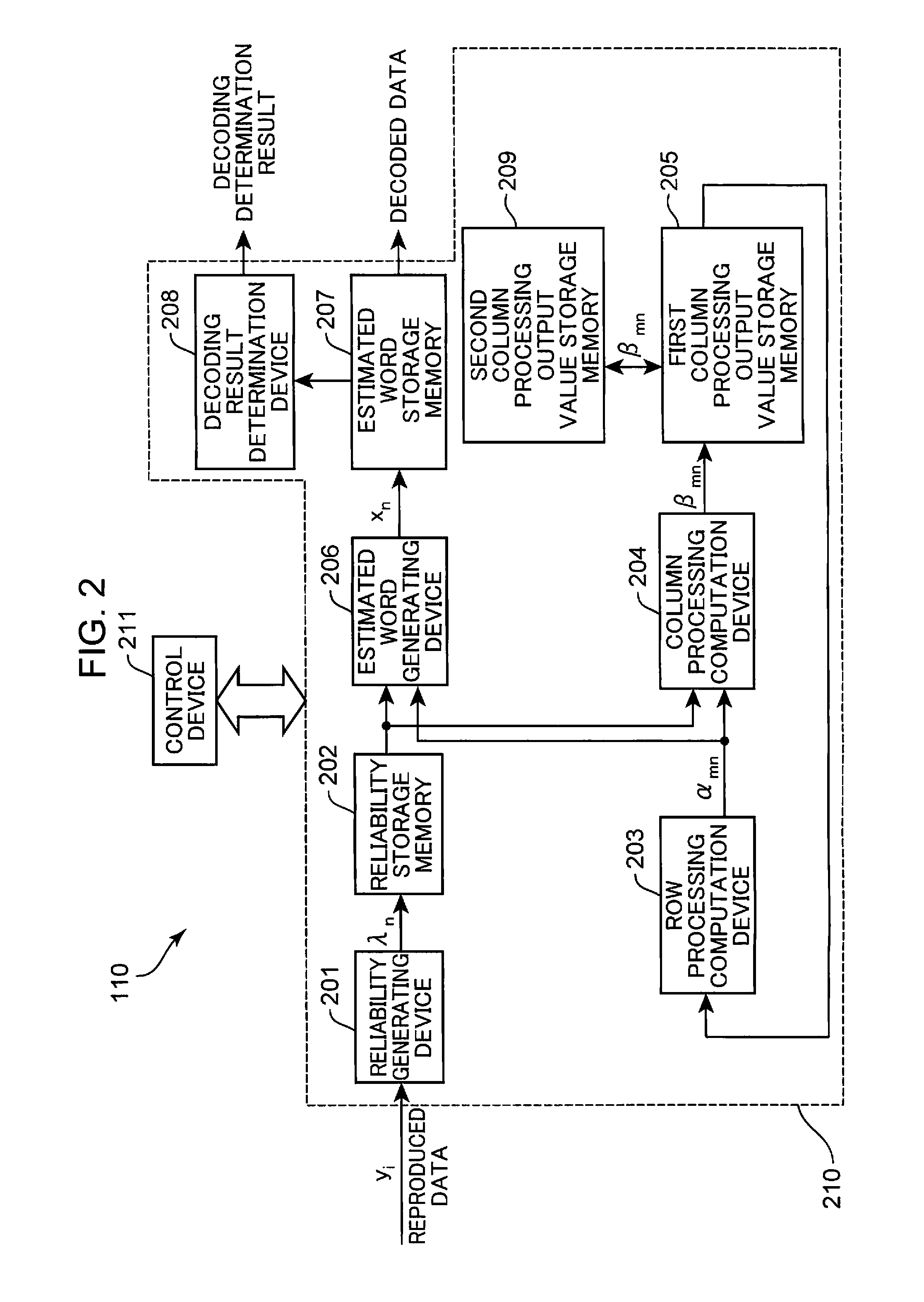
[0037]The decoding apparatus and decoding method according to Embodiment 1 of the present invention will be explained below in greater detail with reference to the appended drawings.

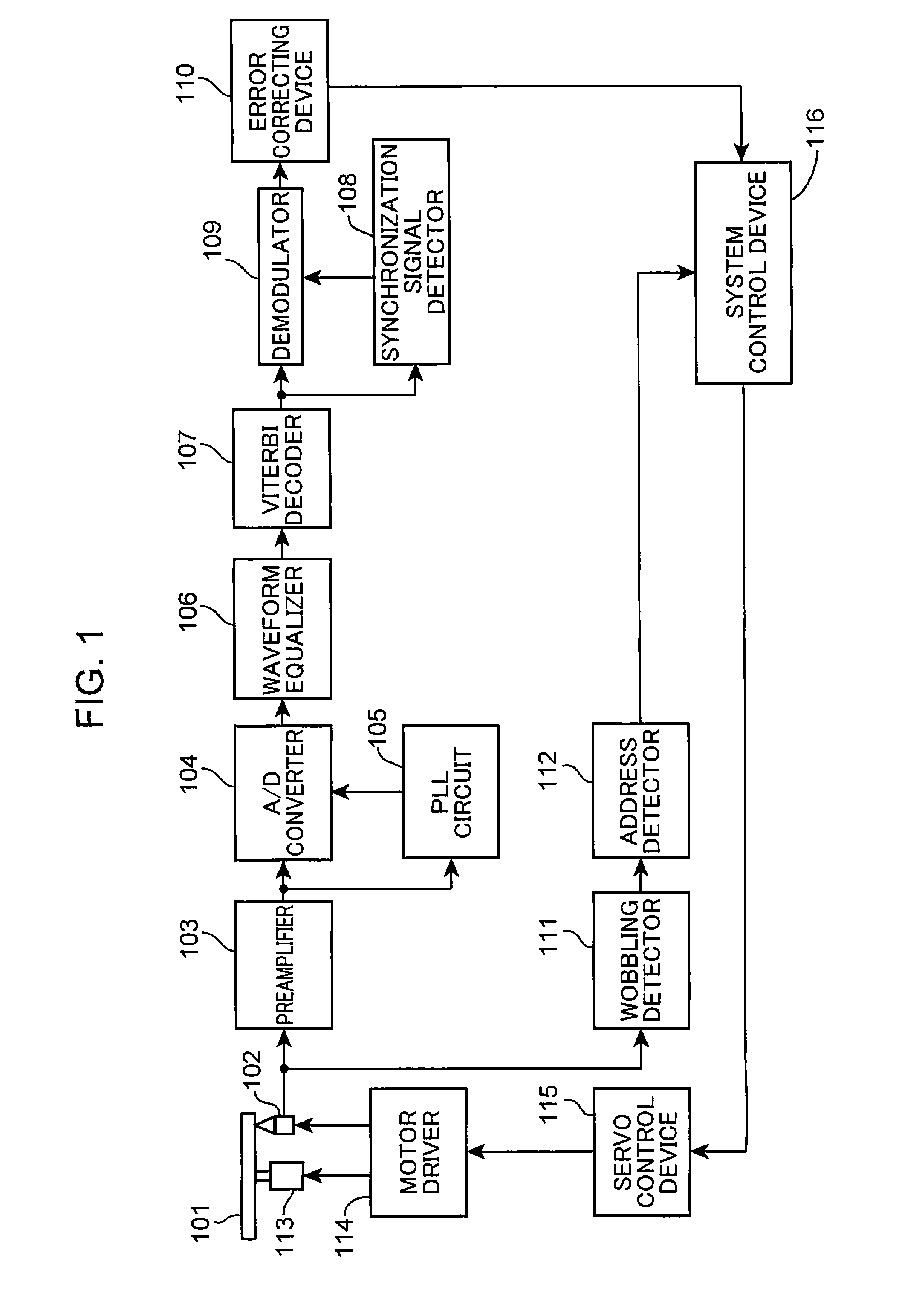
[0038]FIG. 1 shows the configuration of an optical disk device according to Embodiment 1 of the present invention. The optical disk device shown in FIG. 1 is provided with an optical pickup 102, a preamplifier 103, an A / D converter 104, a PLL (Phase Locked Loop) circuit 105, a waveform equalizer 106, a Viterbi decoder 107, a synchronization signal detector 108, a demodulator 109, an error correcting device 110, wobbling detector 111, an address detector 112, a spindle motor 113, a motor driver 114, a servo control device 115, and a system control device 116.

[0039]The optical pickup 102 irradiates an optical disk 101 with a light beam, detects a reflected beam from the optical disk 101, and outputs a reproduction signal corresponding to the detected reflected beam. The preamplifier 103 amplifies the repro...

embodiment 2

[0117]The decoding apparatus and decoding method according to Embodiment 2 of the present invention will be described below in greater detail with reference to the appended drawings.

[0118]FIG. 8 is a detailed configuration of the error correcting device according to Embodiment 2 of the present invention. The configuration of the optical disk device according to Embodiment 2 is the same as the configuration of the optical disk device according to Embodiment 1 shown in FIG. 1 and the explanation thereof is herein omitted. In FIG. 8, constituent elements same as those of the error correcting device of Embodiment 1 shown in FIG. 2 are assigned with like reference numerals and the explanation thereof is herein omitted. The difference between the error correcting device of Embodiment 2 shown in FIG. 8 and the error correcting device of Embodiment 1 shown in FIG. 2 is that the error correcting device 110 is provided with an estimated word reliability storage memory 501 instead of the secon...

embodiment 3

[0133]The decoding apparatus and decoding method according to Embodiment 3 of the present invention will be described below in greater detail with reference to the appended drawings. The configuration of the optical disk device according to Embodiment 3 is the same as the configuration of the optical disk device according to Embodiment 1 shown in FIG. 1 and the explanation thereof is herein omitted.

[0134]The configuration of the error correcting device in Embodiment 3 is the same as that of the error correcting device in Embodiment 2 illustrated by FIG. 8. Therefore, the error correcting device of Embodiment 3 will be explained with reference to the error correcting device shown in FIG. 8.

[0135]FIGS. 11 and 12 are flowcharts illustrating the decoding processing performed by the error correcting device of Embodiment 3 of the present invention.

[0136]The difference between Embodiment 3 and Embodiment 2 of the present invention is that the step of generating new estimated word xn′ is pe...


PUM

PropertyMeasurementUnit
processingaaaaaaaaaa
processing computationaaaaaaaaaa
column processing computationaaaaaaaaaa

Abstract

A control device inputs reliability information on the same data block a plurality of times into a reliability storage memory. A reliability generating device generates a reliability information by performing computation processing based on a stochastic computation by using reliability information generated in the previous cycle that has been saved in the reliability storage memory and reliability information generated in the present cycle, and saves the reliability information generated in the reliability storage memory when the decoding is performed by using reliability information on the data block the same as that in the previous cycle. A column processing computation device computes a column processing output value by using the reliability information generated and saved in the reliability storage memory and a row processing output value.

Description

TECHNICAL FIELD[0001]The present invention relates to a decoding apparatus and a decoding method for decoding data by using a plurality of signals with respect to a section where an error has occurred.BACKGROUND ART[0002]As the density level in storage devices such as magnetic disk devices and optical disk devices has been growing, a variety of techniques have been used in recent years to acquire data correctly from the signals read from the storage devices. Examples of the conventional techniques include error detection, correction processing, and retry processing by which the reproduction operation is retried when a reproduction error is detected. For example, in the retry processing performed in an optical disk device, signal quality of reproduced data is improved by changing various retry parameters such as focus offset or signal amplitude and reproducing again the error location.[0003]Further, a method for reproducing a plurality of times the same region and calculating an arit...

Claims


Application Information

Patent Timeline
Patent Type & Authority Patents(United States)
IPC IPC(8): G11C29/00H03M13/00G06F11/10H03M13/11G11B20/18H03M13/41
CPCG06F11/10G11B20/1833H03M13/1111H03M13/1128G11B2020/185G11B2220/2537H03M13/41
Inventor FUJIMOTO, KEISUKEHINO, YASUMORI
Owner PANASONIC INTELLECTUAL PROPERTY MANAGEMENT CO LTD
Why Eureka
Try Eureka