
Catalytic reaction with reverse-flow regeneration

a reverse-flow regeneration and catalytic reaction technology, applied in the field of chemical reaction processes, can solve the problems of combustion control problems, risk of leaving the bed, and inhomogeneous proportion of coke in the reactor

Active Publication Date: 2016-02-16
ARKEMA FRANCE SA
View PDF5 Cites 2 Cited by
  • Summary
  • Abstract
  • Description
  • Claims
  • Application Information

AI Technical Summary

Benefits of technology

This patent describes a process for converting chlorinated compounds to fluorinated compounds using hydrogen fluoride. The process has several benefits. First, it produces little or no coke, which indicates that the catalyst is efficiently utilized. Second, it reduces pressure drop by restructuring the catalyst bed. This makes the process more economically viable for industrial applications. The patent also provides details on the types of chlorinated compounds and fluorinated compounds that can be used in this process. Overall, this technology allows for the efficient and economical production of fluorinated compounds.

Problems solved by technology

For example, in exothermic reactions such as combustion reactions, a hot front has a tendency to form in the reactor when the reaction starts, and this hot front has a tendency thereafter to move in the bed of the reactor in the flow direction, until optionally exhibiting a risk of leaving the bed.
However, the proportion of coke in the reactor is not homogeneous: there is, in principle, more coke accumulated toward the inlet of the reactor than toward the outlet thereof.
This poses a combustion control problem.

Method used


Image

  • Catalytic reaction with reverse-flow regeneration

Examples


example 1

According to the Invention

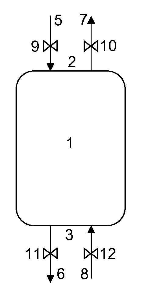
[0166]A reaction tube (1) made of 316L stainless steel, having an internal diameter of 22 mm and a height of 1 m is submerged vertically in a salt bath (KNO3, NaNO3, NaNO2 eutectic mixture) provided with a resistance heater and agitated by nitrogen bubbling. This device makes it possible to efficiently carry out the heat exchanges with the reactor. The temperature inside the reactor is monitored by 14 thermocouples located in a thermocouple sheath having an external diameter of 4 mm positioned in the center of the reaction tube. The reaction tube is charged with 0.337 liters of a PW / TiO2 catalyst, prepared according to example 1 of patent application WO 2013 / 18915.

[0167]In a reaction phase, a positive displacement pump and 2 mass flow regulators make it possible to respectively send a mixture of glycerol / water, nitrogen and air via a line (5) into an electrically heated vaporizer electrically connected to the end (2) of the reactor located at the top thereo...

example 2

Comparative

[0177]The conditions from example 1 between 0 and 24 h are reproduced.

[0178]The regeneration step is carried out from t=2 h to t=4 h without flow reversal.

[0179]From t=2 h to t=2 h 05, the pressure in the reactor is reduced to atmospheric pressure and the reactor is sparged with a stream of 416 Nl / h of nitrogen via the line (5). The regeneration phase is then started by injecting, at atmospheric pressure, a stream of 169 Nl / h of an air / nitrogen mixture containing 3.3% by volume of oxygen into the top end (2) of the reactor via the line (5). The temperature of the molten salt is brought to 315° C. It is observed that the temperature in the catalyst bed passes through a maximum of 337° C. at the start of regeneration (“hot spot”) then decreases. Starting from t=3 h, 169 Nl / h of an air / nitrogen mixture containing 7% by volume of oxygen is injected. At t=4 h 30, the temperature of the molten salt is reduced to 295° C.

[0180]The conditions of example 1 between 4 h and 6 h are t...


PUM

PropertyMeasurementUnit
temperatureaaaaaaaaaa
boiling pointaaaaaaaaaa

Abstract

The invention concerns a chemical reaction process performed in a reaction chamber (1) which contains a catalyst bed, the reaction chamber (1) comprising a first end (2) and a second end (3), opposite the first end (2), the process involving alternately: a reaction phase, in which a reaction flow passes through the reaction chamber (1) from its first end (2) towards its second end (3); and a catalyst-regeneration phase, in which a regeneration flow passes through the reaction chamber (1) from its second end (3) towards its first end (2). The reaction chamber (1) preferably consists of a plurality of separate reaction compartments containing a catalyst bed and a heat-exchange system for exchanging heat therebetween.

Description

[0001]This application is a National Stage application of International Application No. PCT / FR2013 / 051296, filed Jun. 6, 2013. This application also claims priority under 35 U.S.C. §119 to French Application No. 1255368, filed Jun. 8, 2012.FIELD OF THE INVENTION[0002]The present invention relates to a chemical reaction process comprising alternate reaction and regeneration phases. The invention also relates to the use of a chemical reactor suitable for the implementation of this process.TECHNICAL BACKGROUND[0003]The use of chemical reactions, especially involving a heterogeneous catalyst, in fixed bed reactors is known. In processes of this type, control of the heat absorbed or emitted represents a critical aspect.[0004]For example, in exothermic reactions such as combustion reactions, a hot front has a tendency to form in the reactor when the reaction starts, and this hot front has a tendency thereafter to move in the bed of the reactor in the flow direction, until optionally exhib...

Claims


Application Information

Patent Timeline
Patent Type & Authority Patents(United States)
IPC IPC(8): C07C45/52B01J19/24B01J8/06B01J8/02C07C17/37C07C51/00
CPCB01J19/24B01J8/025B01J8/0278B01J8/065B01J19/249C07C45/52B01J2219/247B01J2208/00893B01J2208/06
Inventor DUBOIS, JEAN-LUC
Owner ARKEMA FRANCE SA
Learn More