Optical scanning endoscope

an endoscope and optical scanning technology, applied in the field of optical scanning endoscopes, can solve the problems of difficult automation and lowered operation efficiency (i.e. yield rate), and achieve the effect of significantly improving the efficiency of soldering operations

Active Publication Date: 2016-03-15
HOYA CORP
View PDF18 Cites 6 Cited by
  • Summary
  • Abstract
  • Description
  • Claims
  • Application Information

AI Technical Summary

Benefits of technology

[0006]The present invention is made in view of the above described circumstances. That is, the object of the present invention is to downsize the diameter of the tip end portion of the optical fiber in the optical scanning endoscope and improve the yield rate in manufacturing the optical scanning endoscope.
[0008]According to this configuration, connection of the wiring member with a plurality of actuators electrically can be accomplished on the plane section of the mounting member; therefore, efficiency in an assembling operation can be improved.
[0009]Optionally, it may be preferable that each of the plurality of soldering lands is arranged on the plane section to be spaced apart from each other at a predetermined interval along the direction orthogonal to the longitudinal direction of the optical fiber. According to this configuration, the wiring member can be arranged to align along the direction orthogonal to the longitudinal direction of the optical fiber; therefore, the efficiency in the assembling operation can be even more improved.
[0011]Optionally, the soldering lands of the plurality of first patterns may be arranged on a proximal-end face side of the plane section, and the soldering lands of the plurality of second patterns may be arranged on a tip-end face side of the plane section. Further, in this regard, it may be preferable that the soldering lands of the plurality of first patterns and the soldering lands of the plurality of second patterns are arranged not to face one another on the plane section. According to this configuration, when the wiring member is connected to the soldering lands, adjoining wiring members may be prevented from being interfered with one another; therefore, the efficiency in the assembling operation can be even more improved.
[0012]Optionally, the plane section may include a plurality of stepwise planes which are formed to be lower in heights thereof from the tip-end face side toward the proximal-end face side; the soldering lands of the plurality of first patterns may be arranged on one of the plurality of stepwise planes which is closest to the proximal-end face; and the soldering lands of the plurality of second wiring patterns may be arranged on a different one of the plurality of stepwise planes from the soldering lands of the first wiring patterns. According to this configuration, arrangement of the wiring member may be divided into the plurality of steps on the mounting member; therefore, interference among adjoining wiring members may be reduced, and the efficiency in the assembling operation can be even more improved.
[0016]According to the configuration of the present invention, wiring connection of the fiber driving unit of the optical scanning endoscope can be conducted on the plane section formed on the mounting member; therefore, efficiency of the soldering operation can be significantly improved. Further, it is not necessary to take extra length (a curve) for the wiring and the like into consideration, but the wiring can be arranged substantially linearly; therefore, the tip end portion of the optical fiber in the optical scanning endoscope may be downsized in the diameter thereof.

Problems solved by technology

However, while an outer diameter of the fiber driving unit 23 is notably small (e.g., φ0.8 mm), an operation to solder the lead wires 12 on the outer periphery of the cylindrical surface at each 90 degrees is difficult to be automated, and when the soldering is operated manually, operation efficiency (i.e., yield rate) is particularly lowered.

Method used


Image

  • Optical scanning endoscope
  • Optical scanning endoscope
  • Optical scanning endoscope

Examples


Embodiment Construction

[0029]Hereinafter, embodiments of the present invention will be described with reference to the accompanying drawings.

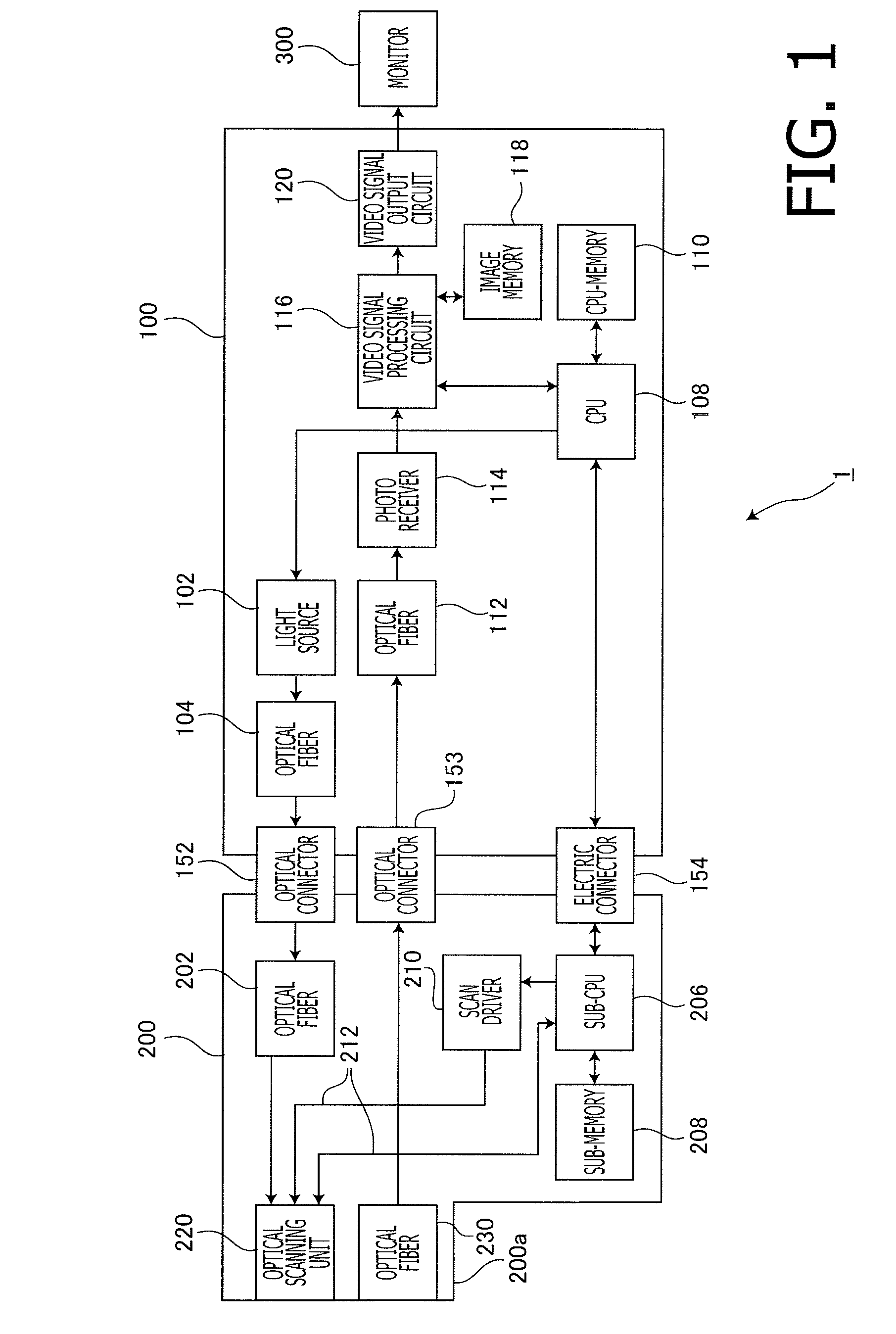
[0030]FIG. 1 is a block diagram to illustrate a configuration of an optical scanning endoscope apparatus having an optical scanning endoscope according to a first embodiment of the present invention. The optical scanning endoscope apparatus 1 is configured with a processor (general-side block) 100, an optical scanning endoscope (patient-side block) 200, and a monitor 300.

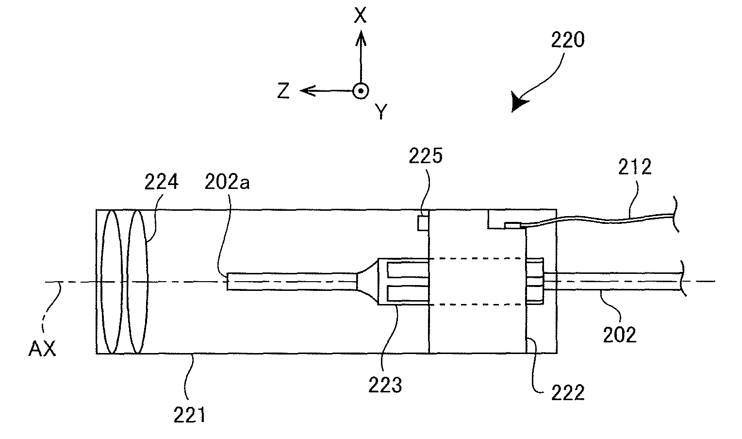
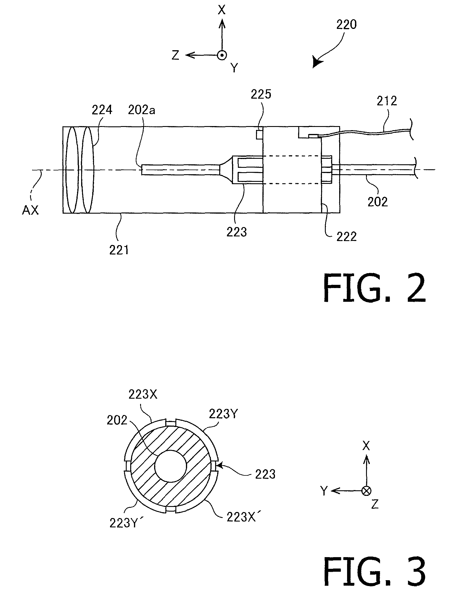
[0031]The processor 100 includes a light source 102, an optical fiber 104, a CPU 108, a CPU memory 110, an optical fiber 112, a photo receiver 114, a video signal processing circuit 116, an image memory 118, and a video signal output circuit 120. The optical scanning endoscope 200 includes an optical fiber 202, an optical scanning unit 220, an optical fiber 230, a sub-CPU 206, a sub-memory 208, and a scan driver 210.

[0032]The light source 102 includes a red-light laser (not shown) to emit red light, ...


PUM


Abstract

An optical scanning endoscope with an optical fiber, and a fiber driving unit with a plurality of actuators which bend side surfaces of the optical fiber by applying a pressing force. A mounting member is a substantially cylindrical molded interconnect device (MID) component which supports the fiber driving unit. A control circuit supplies driving signals to each of the actuators to control the bending amount and direction of the optical fiber. A wiring member electrically connects wiring patterns on the mounting member with the control circuit. The mounting member has a planar surface section at one proximal-end-surface side of the cylindrical outer-peripheral surface. The wiring patterns include at least first patterns having one end portion disposed on the planar surface section to form soldering lands. The other end portions are electrically connected to the actuators on the proximal-end surface of the mounting member. The wiring member is connected to the soldering lands.

Description

TECHNICAL FIELD[0001]The present invention is related to an optical scanning endoscope, which scans an observation portion optically by light guided through an optical fiber and receives the light reflected on the observation portion to form an image. More specifically, the present invention is related to an optical scanning endoscope with a fiber driving unit mounted on the optical scanning endoscope, which is configured with an MID (Molded Interconnect Device) component.BACKGROUND ART[0002]In recent years, an optical scanning endoscope, which scans an observation portion optically in a spiral form by light guided through an optical fiber and receives the light reflected on the observation portion to form an image, is suggested (e.g., U.S. Pat. No. 6,294,775 and Japanese Patent Provisional Publication No. 2010-162089). The optical scanning endoscope is equipped with a single-mode optical fiber in an endoscope therein, which is held in a state of a cantilever by a piezoelectric actu...

Claims


Application Information

Patent Timeline
Patent Type & Authority Patents(United States)
IPC IPC(8): G02B26/10G02B23/24A61B1/00G02B23/26
CPCG02B26/103A61B1/00172G02B23/24G02B23/2476G02B23/26
Inventor ITO, SHUNICHITAKAHASHI, MASAO
Owner HOYA CORP
Why Eureka
Try Eureka