Soil gas system and method

a gas system and soil technology, applied in the field of soil remediation, can solve the problems of sve system power consumption, sve system installation and extraction wells can be relatively expensive, and people, other animals and plants can suffer serious harm, etc., to achieve low permeability material, reduce compaction, and maintain the porosity of fill material

Active Publication Date: 2016-03-22
COUNCIL III EDWARD AUGUSTUS
View PDF5 Cites 3 Cited by
  • Summary
  • Abstract
  • Description
  • Claims
  • Application Information

AI Technical Summary

Benefits of technology

[0009]A system for intercepting, treating and venting of soil gas from contaminated soil includes a least one borehole, a gas permeable liner, and porous fill material. The borehole has an inwardly facing outer wall of the soil and a top end open to the atmosphere above said ground level to allow unimpeded flow of gases, defines a borehole cavity. The liner is in borehole against the outer wall and around the borehole cavity. The liner prevents migration of fine grain particles from the soil into the borehole cavity. The fill material fills the borehole cavity and has a porosity significantly greater than the soil. The fill material can include materials to retard and degrade contaminants in the soil gas such as organic carbon, reactive iron and nutrients for microbial activity. The system can also include a hollow, slotted aeration tube with a diameter smaller than the borehole that extends through said fill material from the top end towards the bottom end of the borehole. Vegetation can be planted in the fill material at the top end of the borehole reduce compaction and maintain porosity of the fill material. Variations in atmospheric barometric pressure pull soil gas from the soil to the borehole cavity and out the open top end of the borehole. The system can also include a ground cover of low permeability material around the top end of the borehole. A method for intercepting, treating and venting of soil gas from contaminated soil includes the steps of providing the system described above and pulling soil gas from the soil to the borehole cavity and out the top end of the borehole with variations in atmospheric barometric pressure.

Problems solved by technology

Soil gas contamination related to volatile organic and inorganic materials is common and can cause serious harm to people, other animals and plants.
Sources of soil gas contamination include leaking underground storage tanks, dry cleaners, leaking pipeline, chemical spills, landfills and transportation mishaps.
Installation of the injection and extraction wells for SVE systems can be relatively expensive.
Power to run the blowers and pumps can be a major cost for SVE systems.
Maintenance of the blowers and pumps adds to the ongoing costs of SVE systems.
Regulatory requirements in many states require these engineered wells be removed after the wells are no longer in use, adding additional cost.
Although the pressure required to open the one way valves used in the second type of PSVE system is very low, the required pressure is still generally greater than normal diurnal barometric variations, so that these valves will only open during meteorological low pressure events.
The one way valves used in the second type of PSVE system are prone to sticking due to insects, dirt, ice, or other materials, and therefore require maintenance.
The engineered wells in the known SVE and PSVE systems project above the ground layer and are therefore limited in location.

Method used


Image

  • Soil gas system and method
  • Soil gas system and method

Examples


Embodiment Construction

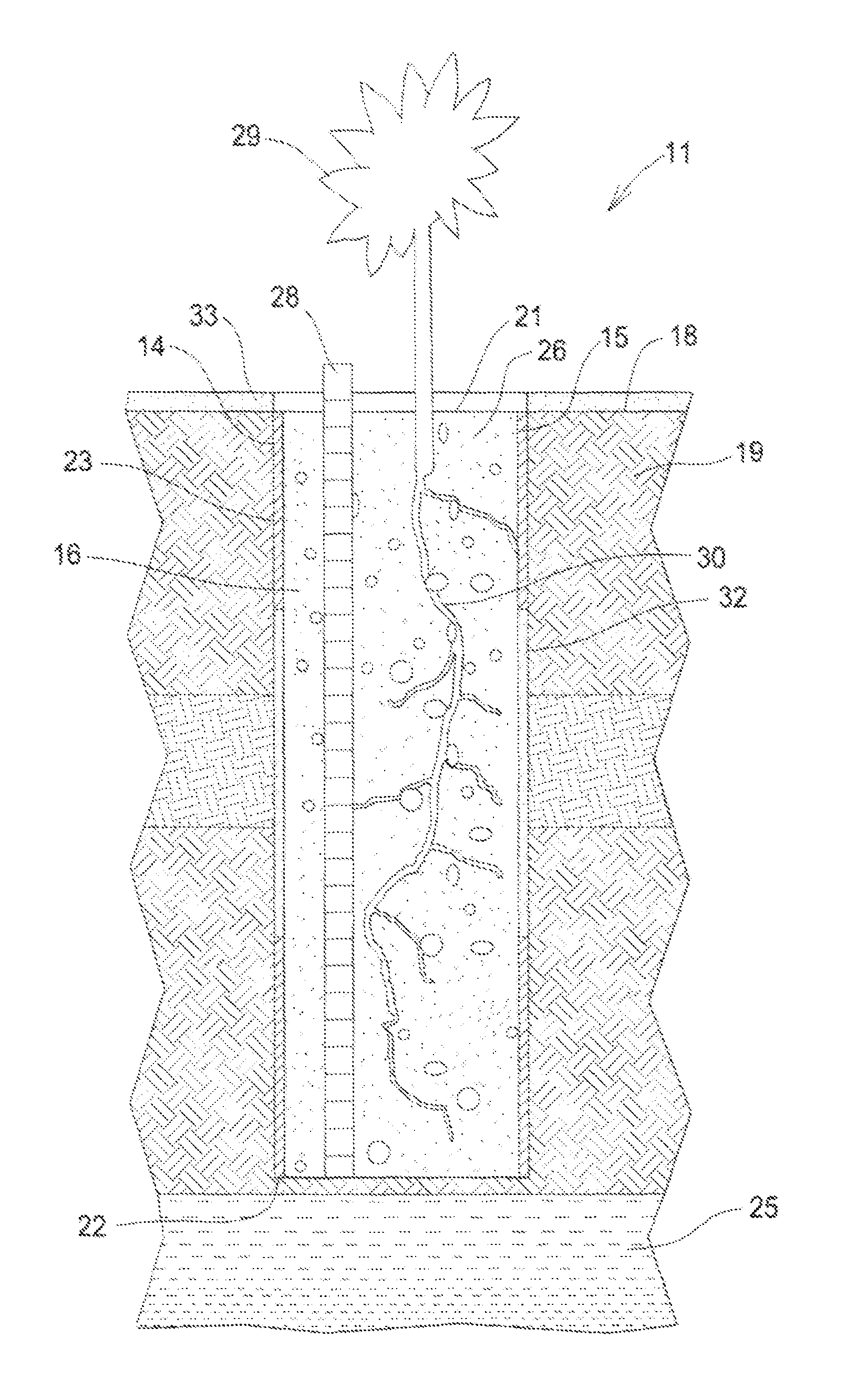
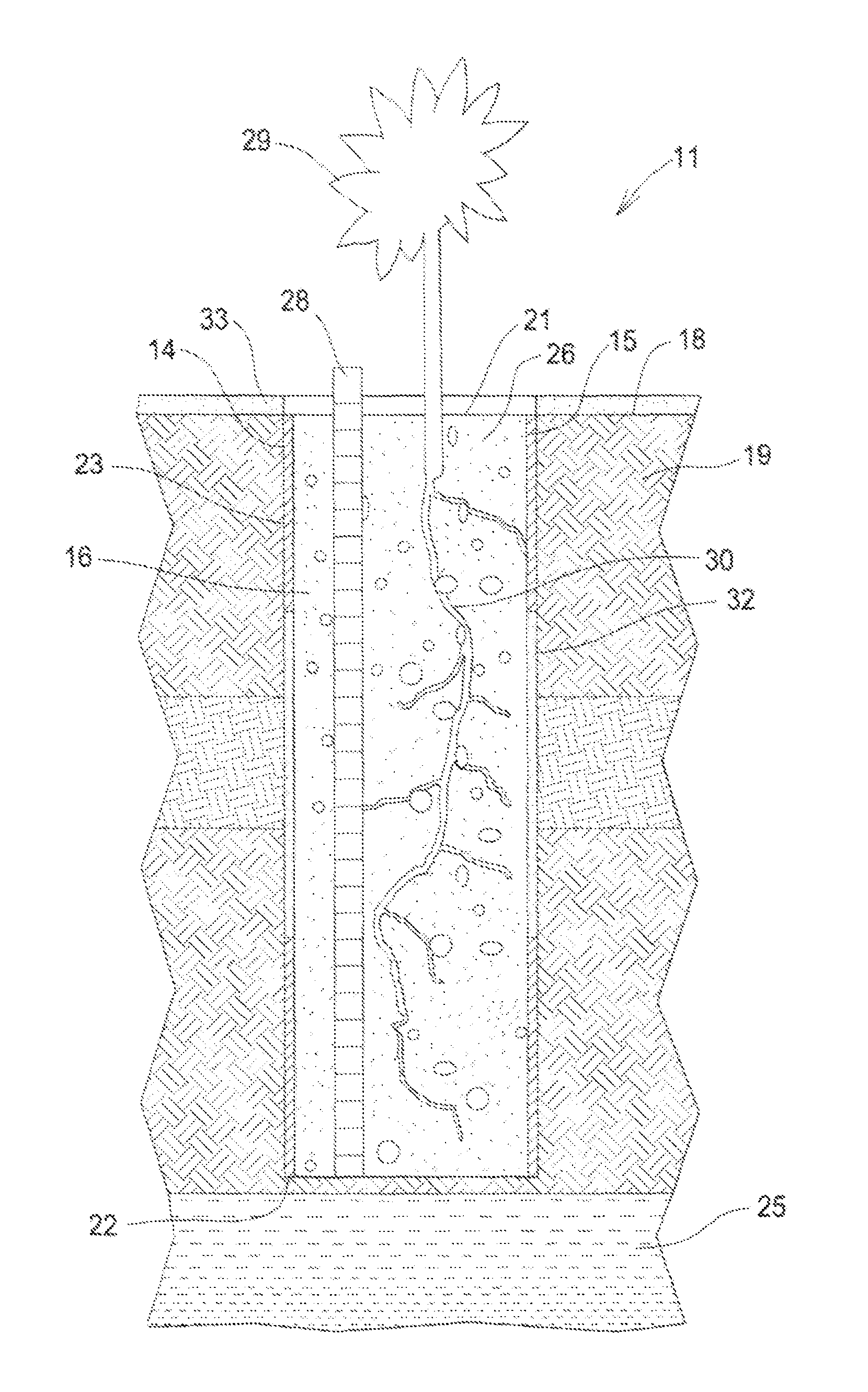
[0012]Referring to the FIGURE, a system 11 for intercepting, treating and venting soil gas from contaminated soil, embodying features of the present invention, includes one or more spaced boreholes 14 each having a liner 15 and fill material 16. Each borehole 14 is drilled from ground level 18 downwardly to a selected depth through the soil 19. The borehole 14 has an open top end 21 at ground level 18, a spaced bottom end 22, and an inwardly facing outer wall 23 of the soil 19 that extends from the top end 21 to the bottom end 22. Preferably the bottom end 22 is above the water table 25. The borehole 14 defines a borehole cavity 26.

[0013]The liner 15 fits into the borehole 14 adjacent to the outer wall 23, and extends from the top end 21 to the bottom end 22. The liner 15 is gas permeable and can be made from organic or inorganic mesh. The liner 15 reduces and prevents fine grain particles in the soil 19 migrating into the borehole cavity 26. The liner 15 can include one or more gas...


PUM


Abstract

A system for intercepting, treating and venting of soil gas from contaminated soil includes a borehole with an open top end, a porous liner against the outer wall of the borehole and porous fill material inside the liner. The fill material can include materials to retard and degrade contaminants in the soil gas. The system can include a slotted aeration tube in the borehole, vegetation planted in the open end of the borehole, impermeable sections in liner, and impermeable ground cover around the top end of the borehole. A method for intercepting, treating and venting of soil gas from contaminated soil includes the system and pulling soil gas out the top end of the borehole with variations in atmospheric barometric pressure.

Description

TECHNICAL FIELD[0001]The present invention relates to soil remediation, and more particularly to a passive system and method for intercepting, treating and venting soil gas from contaminated soil.BACKGROUND ART[0002]Soil gas contamination related to volatile organic and inorganic materials is common and can cause serious harm to people, other animals and plants. The United States spends billions of dollars each year treating soil gas contamination. Sources of soil gas contamination include leaking underground storage tanks, dry cleaners, leaking pipeline, chemical spills, landfills and transportation mishaps.[0003]The vadose zone, between the ground surface and the water table, generally consists of subsurface sediments that were deposited in substantially horizontal layers. Soil gases exist in the subsurface layers often at pressures slightly higher than atmospheric pressure due to microbial respiration, physiochemical influences on contaminants, periodic decreases in barometric pr...

Claims


Application Information

Patent Timeline
Patent Type & Authority Patents(United States)
IPC IPC(8): B09C1/00B09C1/10
CPCB09C1/005B09C1/10B09C2101/00
Inventor COUNCIL, III, EDWARD, AUGUSTUS
Owner COUNCIL III EDWARD AUGUSTUS
Why Eureka
Try Eureka