Image representation supporting the accurate positioning of an intervention device in vessel intervention procedures

a technology for intervention devices and image representations, applied in image enhancement, angiography, instruments, etc., can solve the problems of difficult registration of anatomic representations with life data, and achieve the effect of accurate positioning of intervention devices

Active Publication Date: 2016-03-29
KONINKLJIJKE PHILIPS NV
View PDF32 Cites 17 Cited by
  • Summary
  • Abstract
  • Description
  • Claims
  • Application Information

AI Technical Summary

Benefits of technology

[0022]The at least one angiogram X-ray image and the at least one live fluoroscopy X-ray image may be acquired with a same X-ray image acquiring device being in an identical image acquisition geometry. In other words, in a vessel intervention procedure, first the angiogram X-ray image may be acquired using an X-ray image acquisition device while contrast agent is present within the vessel region of interest. At a later stage of the procedure, i.e. when the intervention device such as a replacement aortic valve is to be positioned within the vessel region of interest, one or more live fluoroscopy X-ray images may be acquired without any contrast agent present within the vessel region of interest using the same X-ray image acquiring device, wherein the image acquisition geometry is the same as when taking the angiogram X-ray image. Furthermore, the radio-opaque device should be at the same position within the vessel region of interest for both the angiogram X-ray image acquisition and the live fluoroscopy X-ray image acquisition. Thus, upon the radio-opaque device being identified in each of the angiogram X-ray image and the live fluoroscopy X-ray image, the two X-ray images may be easily registered to one another in order to generate the angiogram-fluoroscopy-registration.
[0026]In order to further support the accurate positioning of the intervention device in the vessel intervention procedure, the proposed medical imaging device may be further adapted for generating visualized positioning marks within the output image representation. For example, an outline of the valve as projected onto the image plane may be visualized within the image representation resulting from the anatomy-fluoroscopy-registration. In addition to the pure anatomy information, this image representation may further include geometrical elements such as a schematic representation of the valve plane (seen in projection as a line or a parallelogram, or a simple shape such as a circle or an ellipse), which may be a key element for valve fine positioning.
[0030]It has to be noted that features and advantages of embodiments of the invention are described herein with reference to different subject-matters. In particular, some embodiments are described with respect to method type features whereas other embodiments are described with respect to device type features. However, a person skilled in the art will gather from the above and the following description that, unless otherwise notified, in addition to any combination of features belonging to one type of subject-matter also any combination between features relating to different subject-matters is considered to be disclosed with this application. Particularly, features can be combined providing synergic effects that are more than the simple sum of the features.

Problems solved by technology

Because features of the vessel anatomy such as e.g. a valve anatomy may be hardly visible in live fluoroscopy X-ray images, a registration of the anatomic representation with the life data may be very challenging.

Method used


Image

  • Image representation supporting the accurate positioning of an intervention device in vessel intervention procedures
  • Image representation supporting the accurate positioning of an intervention device in vessel intervention procedures
  • Image representation supporting the accurate positioning of an intervention device in vessel intervention procedures

Examples


Embodiment Construction

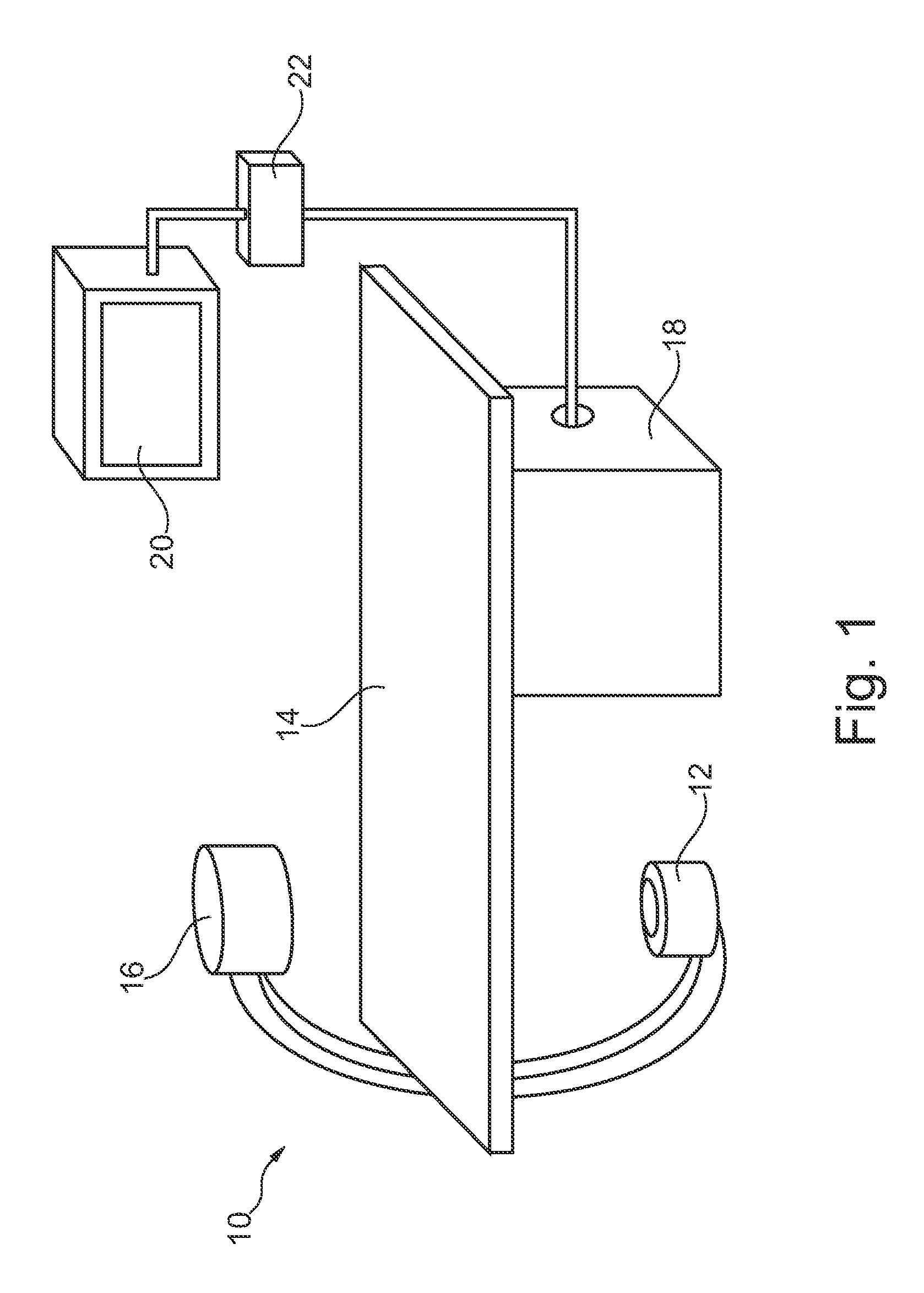
[0036]FIG. 1 schematically shows an X-ray imaging system 10 for use in a catheterization laboratory with an examination apparatus for accurate positioning for heart valve replacement. The examination apparatus comprises an X-ray image acquisition device with a X-ray source 12 provided to generate X-ray radiation. A table 14 is provided to receive a patient to be examined. Further, an X-ray image detection module 16 is located opposite the X-ray source 12, i.e. during the radiation procedure the subject is located between the X-ray source 12 and the detection module 16. The latter is sending data to a data processing unit 18, which is connected to both the detection module 16 and the X-ray source 12. Furthermore a display device 20 is arranged in the vicinity of the table 14 to display information to the person operating the X-ray imaging system, i.e. a clinician such as a cardiologist or cardiac surgeon. Preferably the display device 20 is movably mounted to allow for an individual ...


PUM


Abstract

A medical imaging device and a method for providing an image representation supporting inaccurate positioning of an intervention device in a vessel intervention procedure is proposed. Therein, an anatomy representation (AR) of a vessel region of interest and at least one angiogram X-ray image (RA) and a live fluoroscopy X-ray image (LI) are acquired. The following steps are performed when a radio-opaque device is fixedly arranged within the vessel region of interest: (a) registering the anatomy representation to the at least one angiogram X-ray image in order to provide an anatomy-angiogram-registration (R1); (b) processing (DP) the at least one angiogram X-ray image and the at least one live fluoroscopy X-ray image in order to identify in each of the X-ray images the radio-opaque device; (c) registering (R2) the at least one angiogram X-ray image to the at least one live fluoroscopy X-ray image based on the identified radio-opaque device in order to provide an angiogram-fluoroscopy-registration; and (d) combining the anatomy-angiogram-registration and the angiogram-fluoroscopy-registration in order to provide an anatomy-fluoroscopy-registration (GTC; RALC). Finally, an image representation resulting from the anatomy-fluoroscopy-registration showing an overlay of live images with the anatomy representation may be output thereby helping a surgeon to accurately position for example a synthetic aortic valve within an aortic root of a heart.

Description

CROSS-REFERENCE TO PRIOR APPLICATIONS[0001]This application is the U.S. National Phase application under 35 U.S.C. §371 of International Application Serial No. PCT / IB2012 / 050441, filed on Jan. 31, 2012, which claims the benefit of European Application Serial No. 11305116.3, filed on Feb. 7, 2011. These applications are hereby incorporated by reference herein.FIELD OF THE INVENTION[0002]The present invention relates to a medical imaging device and a method for providing an image representation supporting the accurate positioning of an intervention device such as an artificialaortic valve in a vessel intervention procedure such as transcatheter aortic valve implantation (TAVI). Furthermore, the present invention relates to a corresponding catheterization laboratory system, a corresponding computer program and a computer-readable medium comprising such computer program.BACKGROUND OF THE INVENTION[0003]Vessel intervention procedures often comprise the task of positioning an intervention...

Claims


Application Information

Patent Timeline
Patent Type & Authority Patents(United States)
IPC IPC(8): A61B6/00A61B6/12G06T7/00A61B5/00A61B17/00
CPCA61B6/481A61B6/487A61B6/504A61B6/5229G06T7/0024A61B6/12A61B5/0033A61B6/4441A61B6/488A61B2017/00778A61B2090/364A61B2090/376G06T2207/10121G06T2207/20221G06T2207/30021G06T2207/30101G06T7/30
Inventor FLORENT, RAOULCATHIER, PASCAL, YVES, FRANCOISNEMPONT, OLIVIER, PIERRE
Owner KONINKLJIJKE PHILIPS NV
Why Eureka
Try Eureka